This chapter deals with ion laser system and ion tube issues; ion laser power supply repair is discussed in the chapter: Ar/Kr Ion Laser Power Supplies. Some model specific repair and related issues may also be found in the chapter: Complete Ar/Kr Ion Laser Power Supply Schematics.
The key here is that neither output of a bridge rectifier (which is most likely at the front end of the power supply) is at Earth Ground potential. They both have a large AC component with respect to Earth Ground. Consider:
                     D1
        H o-----+----|>|-------+---------+-----o DC+
               ~|    D2        |+        |
      In from   +----|<|----+  |       +_|_
      AC line        D3     |  |      C ___
                +----|>|----|--+       - |
                |    D4     |            |
 ---+-o N o-----+----|<|----+------------+-----o DC-
    |          ~   Bridge       -
    +-o G o------------------------o Earth Ground (also connected to scope)
   _|_
  ///
Hot (H) and Neutral (N) are tied together at the electrical service panel. Now think about what would happen if the scope test probe ground lead was connected to DC- without an isolation transformer. This would basically short out D4 and put D2 directly across the line (among other things). Not good. With an isolation transformer for the power supply, there will be no fireworks. However, an isolation transformer for the scope will not help unless it has an isolated ground, or the scope ground is disconnected.
Take extreme care when making measurements. The laser itself should be powered via an isolation transformer if possible. This is much preferred to isolating the test equipment (or - gasp - cutting their grounding pins or using 3 to 2 pin grounding adapters without attaching the third wire). The reason is that isolating the power supply prevents the situation where accidental contact between the internal circuitry of the power supply or laser head, and earth ground, will be a shocking experience. If only the test equipment is isolated, the power supply and laser are still live with respect to earth ground. This will permit measurements to be made, but is still extremely dangerous.
For tests of the control circuits or even the igniter, a modest size isolation transformer will be adequate. These are readily available new or surplus, or can be constructed inexpensively. It's only when the tube starts that the high current capability will be required. See the document: Troubleshooting and Repair of Consumer Electronic Equipment for more info on isolation transformers.
Note that most isolation transformers DO NOT isolate the earth ground (third prong). Thus, if using one on an oscilloscope where signal ground and earth ground are tied together, there will still be fireworks, and the scope cabinet will still be a potential shock hazard (for the return from the live laser).
Ultimately, safe troubleshooting of line-powered and/or high voltage systems comes down to good work habits - one hand in a pocket, elimination of Earth Ground points to touch, not working in hip-deep salt water, etc.
Also see the document: Safety Guidelines for High Voltage and/or Line Powered Equipment.
For example, the following table shows the expected MTBF hours for an ALC-60X/Omni-532 compatible tube (specific model unknown) as a function of beam current:
   Plasma   -------- Laser Output Power (mW) --------
    Tube     Multi- ------ Gaussian TEM00 Mode ------
   Current    mode           ------- Pure Line ------
   (Amps)   -- All Lines --   457 nm  488 nm  514 nm   Lifetime (MTBF) Hours
  ---------------------------------------------------------------------------
      4        20      10       1.0      7.0     0.0      15,000 - 25,000
      6        50      30       2.0     17.6     7.5       8,000 - 15,000
      8       110      70       5.0     27.0    23.0       4,000 -  6,000
     10       220     130      10.0     44.0    42.0       1,500 -  2,000
     12       325     200      15.0     60.0    68.0       1,000 -  1,500
     14       430     280      22.0     81.0    98.0         500 -  1,000
Thus, it makes a lot of sense to run at the lowest power that will be adequate
for the application whenever possible to maximize tube life (not to mention
keep your utility bills within reason!). For a multiline tube, reducing
current may still get you the particular color(s) you need with adequate
intensity and/or acceptable color balance. However, each model/age tube will
have a different balance of lines at a given current (i.e., of the 10 for
argon and 11 for krypton). Also see the section:
Laser System Life.
Note: The power output numbers, above, look like they apply to a very 'hot' or new tube - at least compared to what you'll typically find in a surplus 60X laser. The actual power (at a given current) for one of these will likely be somewhat lower. Keep this in mind if you see an advertizement for a 400 mW 60X! Also see the section: Expected Output Power from Surplus or Previously Owned Ion Lasers.
(From: Steve Roberts (osteven@akrobiz.com).)
10 A is absolute max on a average 60X tube. I once talked to a engineer who was on the 60X project, and he prefers 9 A as the upper limit. Keep in mind that's a MTBF for a new tube, not a used one. Also note that the factory sells lasers from 5 mW and up, therefore you don't know what you have in the cavity.
The American PSU can in theory source 14 amps for short periods of time. However this is only on a modified unit. 10 Amps is about what they can do. 11 amps runs the pass-bank way hotter then its 100% duty cycle temp without readjustment, in my opinion.
However I've never seen a manual for it and am going from what I've learned from trial and error. A few newer compact FET based gold boxes made by Marlin can only do 9 amps. Above that they go into meltdown, so one has to be careful.
As for maximizing life of a small to mid-size tubes (up to 2 or 3 W) where the laser is to be used intermittently (between shows, for example - say 10 minutes on, 20 minutes off), it is better to drop it back to idle (the lowest current which will maintain the discharge) when the beam is not needed rather than shutting down completely. (However, large frame ion lasers should be turned off entirely between shows - they like to run at one particular current.)
(From: Steve Roberts (osteven@akrobiz.com).)
For larger water-cooled ion lasers reducing current increases tube life only up to a point. However, running consistently at low idle is not good for the tube. On short frame lasers there is a certain reference current. You can go about 6 to 7 amps below it and an amp or two above it and still have decent lifetime. This point is determined from the factory data sheet for a given tube and by users' experience.
Running above this window leads to quickly shortened tube life. Running much below it can result in plasma instability and PSU damage, as well as eventual tube damage. The rebuilder I used to work with stressed running consistently for long periods at the reference current as the best way to avoid warranty repairs, and I'd tend to believe him.
Also, depending on your PSU design, it is often recommended that you start at the high end of the current range. Otherwise, damage to the PSU and tube cathode may result from repetitive start pulses when the tube doesn't catch but just flashes. Some power supplies will start at a high current regardless of the control settings, and then drop back to the selected current or power.
On white light lasers, or pure krypton, there usually is a 'knee' curve in the plot of light output versus current where the krypton lines really take off. I'd find the knee point for my tube and see where it is versus the factory recommended current and run right around that region or a little above it. What I mean is if you look at the Kr gain curve, you'll see its a very gentle slope from laser start to usually a point around the mid current range, where the line in the plot starts to shoot nearly straight up. If the tube is set up right, that breakpoint should be way below the recommended operating current. The knee point will shift higher as the laser ages, and Kr adsorption rates are much higher then Ar rates. 647/568 nm balance is a good indicator of tube pressure, lower pressures favor yellow, however red has much more gain then yellow, so you'll always see some red.
Owning a good power meter and logging line power on a weekly basis with a prism is a good idea. One of the problems of owning a high power argon or mixed gas is that laser ownership at a point stops becoming science and turns into somewhat of a art.
OK, here are the gory details:
(From: Steve Roberts (osteven@akrobiz.com).)
Lifetime decreases exponentially with current, and you can get to the high speed end easily enough. (See the chart in the section: Argon/Krypton Ion Laser Tube Life.) At currents not much over 10 amps, assuming you have a power supply with enough spare output compliance to not burn up, first thing that happens is it outgases from the cathode and bore, so that's the LAST time it lights. Then she starts sputtering and flashing, at this point some will just wink out from overpressure. If the pressure was low enough to begin with, now the anode starts glowing red very bright, and if it doesn't crack off, and if the cathode feed-throughs hold, and the bore doesn't crack from shock, you'd see maybe a watt or so for a few seconds until the cathode goes dead from meltdown or the return bores could no longer handle the flow.
If you did reach this region, getting the cathode material off the stems and replacing the etched insides of the Brewster windows is hard. You can see the particulates accelerate inside the tube from the intracavity light and they go right to the windows at HIGH speeds, glowing like little fireflys and acting like fast little cruise missiles and stick when they hit the window. If they bounce, they go into the returns where the charge is more neutral.
By this time the gas returns will be filled with crud, and when it cools off and you try to relight it will probably find the returns mucho more interesting then the bore.
Interestly enough, new tubes are the hottest until they season in. It's the Brewster windows, cathode, and pressure that determine tube life.
Hint: Got Brewster windows that are clean both inside and outside with good tube voltage, a positive delta-T, and good magnet?, and yet no matter what you do you get no power, put in two high reflectors for a while, ramp up the current and get rid of your color centers in the windows. This is a last resort sort of thing for bigger lasers.
The former Soviet Union and a few U.S. researchers developed some neat tricks to avoid these things and get to 500 to 1,000 watts, but I m not talking. :-) The tricks are not all that easy to do outside of a lab anyways and they fry the coatings off the optics fast.
HGM Medical, the surgical arm of American Laser, made some glycol cooled things roughly the size of a 60X. A water-to-air heat exchanger is built in. Bore sizes are similar, but the changes are in the gas returns, anodes, stems, tube pressure, PSU etc. They do 3.2 watts new at the OC, for a few seconds at a time at a VERY VERY low duty cycle. The limits are the anode and pressure, the anode is air cooled. If you hold the treat pedal down for more then 20 seconds, the power drops off like a falling stone as the pressure rises until the overtemp switch cuts out to protect the tube. Then you need to set for about 5 minutes and it comes back. These were for eye surgery, and the eye surgeon rarely needs the full 3 watts, 200 to 500 mW delivered power to the eye is more typical. Also the OC transmission and lasing threshold is a lot different on a power on demand tube. You may not get enough transmission on a normal X optic. They usually have PC in the part number and a diode aiming beam, since the tube doesn't lase until needed, call it fire on demand, once the tube gets stable, then the shutter opens.
Factory manuals and practical experience are wonderful. ;-)
Here are some more of the gory details, if you can stand them!
The following take place in NO particular order: They are heat related and plasma/pressure related fast failures!!!
The maximum limits are 700 A/cm2 for graphite and 850 A/cm2 for BeO. It's somewhat higher if there are no gas returns being a tradeoff between mechanical strength and radial thermal conductivity to cooling water. However, the tube will suffer from cataphoresis (gas migration) if it there are no returns. Gas returns internal to the BeO weaken it and raise thermal resistance. (This information from: Kesik and Siejca, SPIE vol. 859, Laser Techonolgy II.)
There's another 10 or so nasties, but I'm outta time, chao!
Buy a bigger tube then you need, turn it down to like less then 1/3 to 1/2 of its design power, cool it well, it will live nearly forever.
                         Filament     Discharge
    Manufacturer/Model     VRMS      VDC at IDC        Typical Output Power
 ------------------------------------------------------------------------------
    American Laser 60X      3.0    107-108 at 10 A  20-40 mW, higher multiline
  Cyonics/Uniphase 2301     3.0      105   at  8 A       5-20 mW 488 nm
       NEC GLG-3030         2.6       85   at 10 A        20 mW 488 nm
  Spectra-Physics 091-93    2.9       80   at 10 A        25 mW 488 nm
  Spectra-Physics 093-91    2.9      110   at 10 A  Greater than 25 mW, 488 nm
Aside from obvious physical damage, there are a variety of conditions that can prevent a tube from lasing or result in a weak beam or one with rings or other artifacts:
(From: Anonymous.)
"Where a tube outputs lower than normal power regardless of optics, alignment, and tube position - assuming the PSU is the correct one and functioning properly - could be low on gas. To find out, take a pair of argon (red) safety glasses (EXTREMELY IMPORTANT!) and power it up. Then look for a red spot on the inside of the anode-end Brewster window. The red fluorescent spot will be the indication of low gas pressure."
To check for cathode sag, with ONLY the filament powered (make sure the high voltage is totally disconnected from the tube - you wouldn't want it to discharge while staring down the bore - or to get your nose zapped!), look through the mirror at the cathode end of the tube to view the interior:
However, Ar/Kr ion tubes will often have some sort of additional optics at one end, either a line selecting prism or ghost suppression wedge. This will make it impossible to easily adjust alignment at that end at least.
WARNING: Both ends (and possible other parts) of the tube are probably line-connected so these procedures are significantly more dangerous than with a typical HeNe laser. Take care. It may be possible to use the approach outlined in the section: Pulsed Operation of an Ar/Kr Ion Tube for checking alignment at least. However, the mirrors will have been adjusted at the factory when the tube was running at normal operating temperature (hot!) so it won't behave quite the same (this is probably particularly true for longer tubes).
One cause of the buildup of a damaging coating on the inside surfaces of mirrors or Brewster windows (usually at the cathode-end) is sputtering. If run with an adequately heated filament and moderate (well within specs) tube current, there will be minimal sputtering. However, with excessive tube current and/or an underpowered filament, sputtering will increase. With some power supplies having a wide compliance range, it is even conceivable that the tube might appear to work (for a while at least) with a filament that has lost all power. (I don't know how likely this is with these high current ion lasers as most power supplies will just drop out if the tube voltage were to climb substantially, as it would under these conditions. However, lower current helium-cadmium lasers have been known to do this with an unpowered or open filament.) The arc could either continue to the filament but with much greater 'cathode fall' (the voltage drop between main part of the discharge and the filament) or even strike to some other part of the tube. Assuming the structure doesn't fail outright, one result will be a large amount of sputtering and rapid overcoating of the cathode-end mirror or Brewster window, rendering the tube useless very quickly.
(From: Anonymous.)
"If an air cooled argon produces rings of actual coherent laser light around the beam that cannot be eliminated by alignment and tube position and optics cleaning then it probably has a lot of hours on it. The source of these artifacts will be a metallic beryllium ring that is formed inside the bore right at its cathode opening."
Hydrogen and helium slip through glass and ceramic, and can stay hidden in certain metals used in tubes. They are also used in processing the porous cathode for various reasons. The heavy argon and krypton ions drive the lightweight hydrogen deep into the bore walls and metal portions of the tube, when a tube sets on the shelf, hydrogen can in some cases seep in from the walls and welds. This happens even in quartz or hard Pyrex, and more slowly into ceramics. Most of the hydrogen originates from welding of the seals and fusing of the ceramic to metal joints in a hydrogen furnace during processing. In glass tubes it can come from the cathode and metal structures.
Hydrogen doesn't ionize easily. Thus it raises the tube pressure while increasing the resistance of the discharge. This can lead to a condition where the tube will not lase. Argon has a wide lasing pressure range but as the pressure climbs too high, the blue and violet lines trail off, the 514 nm and 528 nm (green) lines get a little brighter, then the green falls off and lasing ceases, even though in some cases the discharge will still start. Any gas in the tube other then argon or krypton diverts energy from the lasing process - some more then others - and can cause cathode poisoning.
Tubes are carefully filled and designed to center the positive column and the negative dark space and negative glow in specific areas of the tube. That's one reason why cathodes are powered by center tapped AC - to move the arc around. When this alignment deteriorates, you get bore wall erosion, localized heating, and other undesirable effects leading to tube damage.
Thus, a tube with large amounts of hydrogen that the getters can't handle needs reprocessing soon as the hydrogen will change the plasma physics in the tube by moving the cathode dark space and other regions of the discharge which promote erosion to places in the tube not designed for erosion. The main damage will be to the cathode, causing a hot spot to form ultimately leading to cathode sag or total failure (filament breakage). In fact, it is this small hot spot, not gravity, which is the most likely cause of cathode sag. The hot spot may also cause the electron emission agents mixed into the cathode matrix to boil off and dump more impurities into the tube. Low tube pressure will also move the discharge back toward the cathode, heating it excessively.
Other impurities have similar damaging effects, including some that are much more reactive with the tube materials. Carbon dust, for example, will be ionized and accelerated toward the windows, damaging them.
You normally leave the end-bells floating. The only time you would connect to a end-bell is when you want to heat the getter. I don't know where the getter is on Cyonics tubes. Often they have a 3rd pin for it, if not, it's in the cathode end-bell. The getter is a corrigated or fan fold ribbon with little tabs sticking out of it located toward the front of the end-bell so it's not directly bombarded by plasma. It is an active device using the floating ions and electrons for activation. Current is passed through it at the factory to convert carbonates to pure metals and to outgas it.
It is not safe to fire the getter on a 60X, I (Steve) have tried it a few imes and a hard start tube becomes a no start tube real fast! For some of their older tubes, Coherent has a getter procedure for a worse case situation where hydrogen has outgassed when the tube sets on a shelf and is thus at high pressure. Otherwise, no manufacturer would ever suggest lighting off the getter. It takes 7 to 10 A to heat the X getter, a ribbon secured to the cathode at one end. So, it really gets heated a bit during normal use. Further heating would just evolve more gas or burn off more material causing it to bury argon and/or liberate whatever it has gettered. The 60X getter is unique in that its coating is on both the end bell wall and the ribbon after its heated.
On other tubes, getters are designed differently. On Lexels, for example, there is a getter in the ballast tank and the whole inside of the tank is coated. A electrode sticks out of the tank to activate the getter at the factory.
The getter ts there mainly to collect hydrogen and water vapor. Having loose H2 (which diffuses out from the welds and brazes which are done in a hydrogen furnace) raises tube voltage and lowers power. That H2 has a tendency to make water vapor which is really hard on the cathode.
(From: Steve Roberts (osteven@akrobiz.com).)
If your tube is getting old and the gas pressure is starting to drop, refill the tube before you start damaging the cathode. Consult a professional to find out what your tube voltage drop should be for a given current. A lower voltage across the tube equals lower gas pressure. Don't wait too long or it won't be possible to rebuild it.
The following comments were stimulated by being told by another laser tech why my customer's laser that had excess argon added by mistake should not be repumped. The tube isn't at quite high enough pressure to do major damage and the excess argon will burn off eventually. Hydrogen, on the other hand, tends to reappear for some reason, often without warning. I think the answer to that would only appear if we were to torture a ticklish Spectra-Physics or Coherent engineer for hours with a feather :-).
You see, I had thought all along that argon was what needed burying by use, and some of it does need to be buried, but what argon that actually outgases gets reburied in the first 15 to 20 minutes, unless a fill valve from a reservoir is leaking or is opened too much by mistake on a big argon. It's not the argon pressure that prevents ignition, but the H2! Hydrogen seeps into the metal during manufacture of the tube, and can in some cases either leak out slowly over time or suddenly appear, most likely from thermal shock.
Hydrogen causes a large increase in tube voltage, makes starting harder and depletes the population inversion, thus reducing power. When hydrogen or nitrogen is in the plasma, it generates large amounts of heat, thus damaging the tube, hydrogen also reacts with the cathode materials, reducing output and damaging the cathode. If a tube goes high in hydrogen and the getters wont clean it up over time, it's time for a rapid repump, to recover the tube from quick failure.
I learned this the hard way today on a customer's 10 watt laser. The previous tech, not knowing he had a PSU problem, assumed it was low tube voltage (discharge), when in fact the tube voltage meter on the front panel was 25 volts out of calibration from a fried resistor. Each fill brought the laser tube up about 3 to 5 >volts on this model, and he did 5 or 6 fills. Thus, the nominal 354 V tube >drop was now actually 374 V and the PSU could still ignite it. But, the blue >and weaker green lines were suppressed by the high pressure. However, the >528 nm line really blossoms when the pressure is high. This is why a new tube >is so hot in the green but then goes blue as it is used and pressure goes down. >The overfilling resulted in a 2.5 watt drop in lasing power.
The net result was at low currents the tube would not lase at all, and it pushed the lasing threshold (current) through the roof. And, getting the unit to its rated power required a current of 34 A instead of 31 A! We were lucky enough to have a factory test sheet on this one with all the detailed measurements. A high pressure tube manifests itself in two ways, it won't lase or lases at greatly reduced power, and the voltage across the tube increases. I have spent many hours on some units thinking I had a alignment problem, when in fact it was real high pressure.
Once I fixed the ignite boost circuit - which was the original problem - the tube did start up but getting it aligned well enough to get any power was a factor of 10 harder then what it would have been at normal pressure.
The gas fill on this unit is not by solenoid, but by two manual valves with a small space between them, you open one, fill the space, close it then open the other to add the small known quantity of gas. The previous tech thought it was necessary to close the fragile refill valves with Vice-Grips(tm), thus ruining the needle valves, he didn't realize the tube takes time to stabilize as the fresh gas has to be pumped to one end of the tube, heated, and then the new pressure would stabilize. This actually takes 15 to 30 minutes per fill.
Some 500 hours of operation from now, it will be where it should be. All this was heard when I hauled the unit to the refurb shop for a more thorough evaluation. However if this were hydrogen outgassing, which raises the firing voltage and damages the cathode, a repump would be required. A repump would have also been required if the pressure was so high that lasing would not be possible, in this case about another 10 volts. When in doubt, call in a expert!
Tube voltage drop is directly related to pressure in a Ion laser, charting the tube voltage is a easy way to monitor your laser, gradual increases in pressure over time suggest a leaky fill valve. Sudden increases in tube pressure suggest a tube that has possibly overheated and been damaged, hydrogen out gassing, or a recently activated autofill system. An autofill system getting out of control could rapidly overfill a tube. If you hear a sudden burst of solenoid valve clicks, something is going on. Most modern fill systems have a double solenoid valve with a small chamber between them, and a larger high pressure argon reservoir. Opening valve number one fills the chamber with a known amount of gas, then valve number one closes and valve number two opens the chamber to the tube. It then takes 5 to 20 minutes before you see a real stable change in tube voltage. Although you will see a sudden jump when the valve opens, it takes awhile for the gas to go against the discharge and flow down the tube. It is wise to let a laser run for 20 to 30 minutes before enabling fill, as well as checking across the tube with a multimeter once in a while to check the panel meter calibration.
Keeping an eye on where the autofill enable switch is set is a good idea. On some older lasers it's a third key-switch position, and the operator is responsible for just pulsing the key momentarily to open the fill system solenoid - until the fill system buzzer stops beeping or the light goes out. That little "fill" button is a tempting thing for a visitor to push on some lasers, especially if the fill card has been rewired or bypassed by a tech tired of having his morning coffee ruined by a loud beeping while his recalcitrant laser stabilized. If you do anything to the fill circuit, carefully recalibrate it to the factory specs or add a extra key-switch to prevent it from firing.
Some older mixed gas and krypton lasers have a bizarre version of the fill system called a "pressure pump". Since some of the the Kr red, yellow and green lines are fussy about lasing pressure, the pressure pump has a third larger chamber besides the fill chamber to pump the tube down. You increase the current, which raises the plasma temp and thus the gas pressure thanks to the laws of Boyle and Charles (remember P = VT?). A series of valves then open to the larger third chamber, which fills with hot gas acting to reduce the bore pressure. Later when you wish to raise the pressure, the third chamber is slowly dumped into the tube. These lasers tend to have a series of special markings on the tube voltage meter, to guide the operator in choosing the best pressure for a given line. The 647 nm red and 568 nm yellow lines share the same upper state. Whether you get red, or yellow, or a mix of both is determined by the gas pressure which favors a certain lower state for the transition. The 647 nm line likes high pressure, while the 568 nm line likes a much lower pressure. Running one of these requires some operator skill, patience, and a good reading of the manual.
Remember, when working with fill systems, patience and care is needed, and time must be given for the tube to stabilize.
Incidentally, if you do much work on lasers, it is wise to buy a cheap DMM, as when working on the laser you can often forget it's still across the tube, then when the tube winks out and restarts, the ignite pulse fries the meter into oblivion. (Or always put the meter before the igniter if you have access to the power supply and account for any wiring/other voltage drops.)
And for those poor souls who would wish to repump a CR52 or other ancient coherent graphite with the vacuum access valves mounted on the reservoir, the valve actuators to hook onto the tube are available from CPC-Cryolab. Now I can't reccommend equipping modern ion laser tubes with O-ring sealed anything, having bad experience with various valves etc. Orings cannot be depended on at the low levels of vacuum used in a ion laser. Graphite tubes have such horrible gas cleanup and release cycles that something was needed to recover the tube if it got over or under pressured. On more modern tubes, a oring or most types of bellows valve is NOT going to stay sealed for more then a couple of days of operation. Nothing beats a copper pinch off or a molten glass seal off. However for a DIY sealed CO2 laser, where air leakage is not going to do much harm, these things are great!
(From: Dan Glassburn (dan@niteliteproducts.com).)
Concerning tube pressures and discharges....
While under normal pressure range, the voltage at a particular current will be related to tube pressure - i.e., lower voltage equates to less pressure and higher voltage equates to higher pressure. However this is only within a particular range of pressure. Many tubes when running out of the normal operating range will reduce voltage then at some point start to increase tube voltage required to keep them ionized. This is more prevalent with solid bore tubes. The disk tubes just won't sustain ionization at lower pressures and higher currents. Many of the solid bore tubes will go into a "chirp" or oscillation which usually will cause havoc with the pass-bank. In the case of an air cooled, higher currents to deliver greater outputs will cause the tube to outgas more, especially if you don't have enough cooling. An easy way to see if the tube is low pressure in a 60X is to drive the current to it's maximum from and idle and see if the tube winks out. Many of the systems on the market do exhibit this symptom, although this is usually not how the customer normally uses the system. To get additional life from a low pressure air cooled, ramp the current up slowly. This allows the gas pressure in the tube to increase slowly and help sustain higher currents.
Bad plasma oscillations usually occur if the tube pressure has decreased to the inversion point, where the impedance transforms from slightly positive to negative. Passing through zero is the trouble point. Oscillations again start occurring if the pressure gets almost too high to light or stay lit. For example, if you have a leak on the pumping station while lit. I recently have had 2 I90s on station and one of them had burned so low that it wasn't lighting. Adding a few puffs of gas made it unstable and only able to stabilize at high current. Puffing in about two volts of gas made it appear stable for a while, but to get ignition in the next few weeks operating at low currents I had to puff in more gas, even though the tube seemed to be at the correct voltage. (For these tubes, the inversion point seems to be a plateau in the curve.) So I finally over puffed it by about 3 volts, and now she always fires on the first pulse. So the worst plasma chirp seems to occur at very low pressures.
Why does a healthy laser cathode climb in power (positive delta-T) when the plasma is lit? Rough explanation: Electron emission is an endothermic cooling process for the cathode. Sure you have to heat it to get it to emit, but it looses electrons, which by definition are a packet of energy. This results in cooling and a lower resistance of the cathode wire so there is an increase in current till the system reaches equilibrium. The cooling is perhaps roughly proportional to the cathode work function times the emission current.
In a healthy ion laser tube with good gas pressure, you have many more positive ions then electrons floating around the tube. Thus, the tube voltage climbs as the beam current increases. There is plenty of gas to ionize, electrons are rapidly adsorbed and used, they have a short mean free path from atom to atom, but lots of atoms to ionize. That short mean free path and higher probability of collision means they have a longer path down the tube, hence the higher voltage.
In a mediocre tube, there are less gas atoms due to lower pressure from plasma driven adsorption, and contaminates floating around the tube to adsorb gas and poison the cathode. But there is still healthy cathode emission, so you have a more of a break even condition - less gain, less ionization occurring, but still the tube is happy, just its failure mechanisms are starting to accelerate because of the lowered pressure. This is observable as less tube voltage climb with current and is the "Inversion Point"
In a low pressure tube, there is a big electron cloud with just a few ions. The ions remaining are energetically accelerated and plasma etch tube structures. The electrons are also highly energetic due to a lack of collisions and thus do even more damage as they pass through the tube. By this time the cathodes emission is probably shot from contamination and plasma etching. Impurities don't get buried if there is no gas to accelerate them into the walls. The plasma is unstable and probably moving around by this point. As you increase tube current, you have a excess of electrons floating around and so the tube voltage actually goes lowers.
So the first thing you do when you get a new laser, is chart the tube voltage versus current and check for a delta-T on the cathode. Delta-T is best observed by using a clamp-on AC ammeter around a cathode lead. Note that a few more modern high tech lasers have constant current transformers or autoswitching PSUs for their cathode and this may not apply to them. Also, if your cathode transformer is not correctly tapped or the buck boost on a older laser is misadjusted, you may not see a delta-T of either sort.
Lowering the cathode current moves the first dark space in the discharge back toward the cathode and can reduce the amount of ions generated, resulting in etching of the cathode's active emitting surface, as well as running the risk of cooling the cathode into the 600 to 700 °C region where cathode sag occurs. Excessively raising the cathode voltage (say .5-.7 volts) results in the outer emitting layer "boiling off" and emission falls off fast, resulting in short tube life. The remaining emitting layer will tend to "spot", i.e., most of the emission will come from the remaining emissive material at a cool spot and the cathode will eventually melt or burn at that region. Its is however better to err on the warm side then then the cold.
Some modern tubes with cathodes that are NOT tungsten-rhenium with a borate matrix or NOT a "dispenser" emitter run at about half the current of older cathodes, i.e., many Coherents now have the recommended cathode amperage stamped on the gas reservoir, and I have received reports from credible people that some Lexels are only consuming 15 to 17 amps instead of the normal 25 to 35 amps. This would be characteristic of a more modern Nitride ceramic cathode. So if in doubt, call the factory with the tube serial number and manufacturing date in hand. I have not yet heard of air cooleds using the expensive lower current cathodes, only the large and medium frames. However the ceramic cathode has a much longer life and greater electron emission.
Thanks to Kim, Dan, and Dale for their contributions on this subject, responsibility for errors or incorrectness is my own. --- Steve)
One contributing cause to cathode sag is something called the "Miller-Larson effect". It's a momentary plastic state in the filament caused by a change in the tungsten grain structure as its temperature passes through the range 600 to 675 °C. This results in a lengthening of the filament, and each time the filament goes through that range on warmup, it gets a bit thinner and a little longer. So, it might make sense to keep your filament on (or at reduced power but above 700 °C) during standby rather than shutting it off completely.
Start plasma can suppress emission from the cathode, and if you have a flakey cathode transformer or one that's borderline, the filament can still be cold. One symptom of a cold cathode is the tube catches and starts for a few seconds but winks out as a stable hot spot won't develop on the cathode until its heated more and the barium kicks in. There is a point as you heat the cathode hotter that there is no gain in emission. So you want to be above the Larson-Miller region and yet not too hot. I just found a excellent book on the lifetime and operation of large radio frequency vacuum tubes in broadcast duty, that's where this is coming from. In fact, the broadcast folks don't shut their cathodes down if the downtime is going to be less then 4 hours, they run them at what's called "Black Heat" at about 800 DegC to avoid the stresses of startup.
(From: Steve Roberts (osteven@akrobiz.com).)
If you just try to run at higher than normal temperature, it will be more likely to destroy the cathode permanently by blowing the emissive barium layer off, depleting it possibly in seconds!
Part of cathode initial processing and reprocessing involves heating the cathode to drive the barium out of the porous tungsten matrix at hotter then operational temperatures, but it must be done in a vacuum at 10-7 Torr. It DOES NOT work in the inert gas.
Thats what the famed car battery trick tries to do, blow the dirty non emitting regions off as dust into the tube and expose a little fresh barium. Thats bad too, its much better to have the tube reprocessed at that point then fill it with dust that will erode the bore and optics.
The more correct thing to try is undercurrent the cathode and invert it. Pure Tungsten has a known sagging temperature region where it is butter soft at 600 to 700 °C. However, the cathode is not pure tungsten - it has rhenium, barium, aluminum and calcium - so the exact softening point is known only to the cathode manufacturers. Normally, the cathode runs at 1,080 to 1,120 °C by design. At 800 at °C it actually starts getting tougher in shear and you're not going to do that well because of the additives. You'll end up cooking and outgassing if not actually melting the nickel or molyB section that joins the tungsten to the kovar in the lead throughs.
So if you want to try inverting it, get it to barely a warm soft red glow visible only in the dark and stay and watch it.
Operation at high currents especially, with improper power supply regulation (resulting in plasma oscillations), overheating, or just long hours of use, can lead to failure of the filament structure, excessive sputtering with degradation of the Brewster windows or mirrors, and other irreversible damage. And, accidents can happen as ion tube are relatively fragile structures. "You dropped the wrench where?" :( Any of these would require a more extensive amount rebuilding commonly called a refurb.
Whether a gas refill or total refurb is involved significantly affects the expenses involved. Depending on how much needs to be done and the size of the tube, the cost could be anywhere from a few hundred to a few thousand dollars. Where it is closer to the low end of this range, either of these is still likely to be a bargain compared to the prices of new ion tubes. For example, for a typical air-cooled laser like the Spectra-Physics 161B, typical list prices for replacement tubes are: 15 to 18 mW - $1,900; 20 to 25 mW - $2,750. Just think of what the biggies cost! OK, I'll give you a hint: You can buy a nice new automobile for the same amount of money!
However, On a small air-cooled ion tube (say less then 350 mW), the cost in materials and labor to do a complete refurb exceeds the cost of buying an entire replacement system surplus (about $1,000 if it's done properly with a new cathode, decent welds, etc.).
For just the refill, there will still probably be many hours of actual work over several days involved to gain access, pump it down, backfill, bake, pump it down again, backfill, bake, etc., and then seal it, with an extended burn-in using an ion laser power supply. During a major portion of this time, the tube will be the sole occupant of the expensive equipment required to perform the refill. If all they do is just put in some new gas and pinch the exhaust tube shut, only half a job was done and it probably won't last long. However, you could get lucky.
The amount of gas used is much greater than just what is needed to finally fill the tube prior to seal-off since each backfill/pump down cycle wastes a lot. However, even where krypton is involved (which is more expensive than argon), the cost of the actual gas is still probably not a major part of the total expense.
In addition to labor and gas that is used, you're paying for overhead in the way of the cost of the vacuum equipment, gas manifolds, inventory of gases and gas bottle rental, power supplies needed to test the tubes, rent, etc.
Refurbs include much more work on top of the gas refill possibly including: cutting out the old cathode (filament and possibly a getter) assembly, cleaning the bore, replacing glass or ceramic to metal seals, installing a new cathode assembly, replacing Brewster windows or mirrors, etc. These steps are even more labor intensive and the cost of the replacement parts in this case IS significant.
How much do you think an aspirin tablet costs to manufacture versus what you pay?? :)
Also see the section: Ion Tube Rebuilding in Your Basement?.
Now, for slightly more details:
(Portions from: L. Michael Roberts (NewsMail@laserfx.com).)
The procedure is actually quite complex. First the laser must be disassembled to remove the tube from the head - this process can take 3 to 6 hours depending on the type of laser head. If the cathode, glass, Brewster windows, etc. are in good shape then the tube can just be re-gassed. If not, these and other parts may need to be replaced - which would require disassembly of the tube. This involves glass blowing and/or replacement of the glass to metal seals (it isn't like you just remove a few screws and replace an O-ring!).
The actual regassing requires that the tube be hooked to a vacuum system with an airtight seal. Then, typically the tube is pumped down in a temperature controlled oven for around 24 hours. The heat helps to get the last remnants of the old gas out of the tube. The tube is then typically flushed with a new gas fill and the procedure repeated. This 'rinse and repeat' is used to remove any trace of contaminants in the tube. After the tube is pumped down and baked for the second time, it is refilled with gas and the seal pinched off. Even the pinching off and sealing of the tube takes great precision and special equipment. The tube is then tested and reassembled into the laser head where it typically undergoes a 24 to 98 hour burn-in to assure that all is well.
The procedure can consume 2 to 3 working days as well as many kilowatt-hours of electricity and involves a major investment in specialized and precision equipment - as well as a few dollars worth of gas. You also have to take into account that it is not always successful the first time and may have to be repeated. It is also possible that the tube can be damaged in the process and additional repairs will be needed - all of this factors into the cost. The refurbishing market is quite comparative and if prices could be any lower, they would!
(From: Steve Roberts (osteven@akrobiz.com).)
Hum, as one who does this from time-to-time, I can perhaps enlighten you a little more. Most lasers are sealed with a pinched off copper fill stem It looks like copper refrigeration tubing, but is actually oxygen free ultra high purity copper, about $60 a foot, and this is pinched off by a $3,500 tool that pinches off the copper and cold-welds it with about 30,000 PSI of force, using carbide dies. Here's the rub, the tube is filled with argon at a few Torr - a very small fraction of atmospheric pressure with argon. Should that pinch operation leak even slowly with a microscopic leak, the tube is shot and the rebuilder will be supplying the laser owner with a new tube, or having to completely rebuild the old one again. One speck of hard dust or a void in the copper is all it takes to ruin that pinch. Why not stick a valve on there you ask? Well, even the best valves leak or worse, will be turned by an overly inquisitive customer, a technician grasping at straws for some unrelated laser problem, or even by vibration of the cooling water. When a laser does have fill valves, they are attached to a another sealed low pressure chamber of argon - they don't exit into air.
When you have tricky steps like that in the process, you have to bill extra to pad your losses when you have parts of the process that are really beyond your control.
The header with lead through seals that holds the cathode has a series of glass to metal seals, each one of which is about $200 in quantity one, with a $250 cathode assembly mounted on it. All of these have to be installed with either a moly-mag or gold-indium braze because the use of any other welding process introduces flux into the tube which poisons the cathode and shortens life. The tube looks like iron, but it's actually nickel or something else exotic and it's a pain in the neck to weld. You have to do a weld with no pits or holes in it, even ones that don't go through the weld, as these trap pockets of gas or flux materials that can come back to haunt you. Indium and gold are two of the most expensive metals on the planet, and a typical large tube braze can contain enough of them in one or two joints to make a very respectable wedding ring. This whole thing has to be baked to 700 °F or more under vacuum, leading to possible cracks from stress where the metal bonds the ceramic. Then, the cathode has to be processed so it activates its electron emitting materials, and you risk burning it out at that point. It's also a risk that you may say, repair a leak, try to repump and then find out the cathode is shot. And then finding yourself cutting into the other end of the tube you just repaired. This can turn into a couple of days of work. Keep in mind that some or all of this must be done in a glove box and clean room to avoid contamination.
The whole vacuum pump and fill valve assembly on the work station must be baked out to drive out water and other organics, using turbo pumps or ion pumps, and if you're doing it right, you also have a $20,000 helium leak tester to spot those tiny leaks that could stop the tube from functioning weeks or months down the road, as well as an equally expensive residual gas analyc-zer to make sure you have a clean vacuum.
Even at $1,500 a repump and $4,000 to $5,000 a rebuild, it takes a lot of rebuilds and repumps to pay for that kind of equipment as well as feed your family and put money in the bank for hard times. This is why many rebuilders offer services beyond fixing lasers or also work on much less fragile YAGs or CO2s to help pay the bills.
If you're in the USA, figure at least about $5000 to $10,000 a year per employee in taxes and health care costs as well. And, the process is tricky enough without having to do your own sales, shipping and answering the phone, so you need some help. When you have lasers needing 30 kW and 6 gallons of water per minute, your facility costs are not cheap. It's about 25$ an hour to run a large frame - much more if you figure in the initial costs and rebuild costs and PSU parts. Heck, some of the fuses in a big one are $40 each!
Don't even get me started on the precision glasswork and polishing it takes to make a hard sealed Brewster window. Now if your making thousands of them, the price does come down a little, but one-offs are time consuming and not cheap.
As for gas prices, 250 liters of moderate purity krypton was quoted to me at $269 (plus hazmat plus the cost of the bottle), with research grade about $60 more. I could only find one place in the US that would sell it in small quantities, as it is now a commodity item for semiconductor manufacture. Everybody else wanted me to take out a contract and the price changed daily as the stock market went up and down. As far as I'm concerned that's not cheap compared to argon at $10 a fill for 2,500 liters.
I used to moan and groan about rebuild costs too until I saw what a cheap 'chop and pump' quickie rebuild does to tube life. Figure a large tube is 8,000 to 30,000 dollars from the factory without installation. That can easily justify the cost for rebuilding a commercial or scientific laser.
(From: Dean Glassburn (Dean@niteliteproducts.com).)
As one of those people that supposedly fleece others on refilling. Along with spending my entire weekend refilling a white light Lexel that just will not stabilize in pressure, I can attest to the difficulties involved.
I always have a problem with people saying that it's just too easy. This is why tube rebuilders and reworkers have such a hard time. Until you do this for a living and find out all the shortcomings and have to explain to your customers why your reprocess only lasted 2 months or why you completely ruined their tube, one should be a little less flippant about saying that there is nothing to it and all the parts can be found cheaply. It must be nice to have a cushy job.
And, if properly done, the equipment alone will cost more than a new 1999 Mustang GT.
Acquiring all the equipment and supplies if you don't already have them set up or have access to a lab just to refill a tube or two is at best justifiable only for its educational value. Just sealing the tube off again without *any* leakage isn't as trivial as it might appear for those with metal fill pipes like the ALC-60X. To do that properly, requires a special pinch-off tool that alone would run you the cost of several replacement tubes or maybe even a new laser!
If you have a few gassed out tubes sitting around heading for the dumpster and access to the proper facilities, by all means go ahead and experiment. You might get one of them to lase and last an hour or two after it is sealed. Or more if you're really lucky. Just don't make stupid mistakes like running the filament when the tube is up to air, letting in air suddenly blowing all sorts of crud over the Brewster windows, and zapping holes in the glass parts with your Oudin/Tesla coil! And, forgetting to cool it in the excitement once there is significant current flowing!
For additional comments on ion laser rebuilding, see the sections: About the High Cost of Refills and Refurbs, Caveat Emptor, and Britt Pulsed Argon Ion Lasers. To get an idea of what is involved in getting started before actually cracking the seal on the tube, see the chapter: Amateur Laser Construction since much of the equipment and techniques that are discussed there will be required
(From: Brian Bohan (camlaser@cambridgelasers.com).)
If you think Laser repair prices are high, you should have seen the price of plasma tubes before reprocessing companies existed!! Over the years we have talked a few customers though basic regassing, if you are seriously interested in trying it yourself, I would be more happy to give you some pointers.
(From: Steve Roberts (osteven@akrobiz.com).)
If you're trying to pump one at home, you need to get the pressure to at least 10-6 Torr during cathode outgassing or they die about 2 minutes after you first light them. Lifetime is proportional to how well you get that cathode matrix sucked out at pump, we try for at least 10-7 Torr or better. Most laser companies and rebuilders use a big ion pump roughed by a cryopump with cryotraps. Death is by loss of cathode emission from surface poisoning and then you get a tube that wont restart. The list of things that will poison a active matrix cathode include nickel, carbon, copper, sulfer, iron, kovar, any gas other then hydrogen and the rare gases, most metals and just about any organic or nitrogen compound. welding and brazing fluxes do it quicker then anything else. everything needs to be TIG welded without flux or else hydrogen furnace brazed. Outgassing the cathode properly takes about 48 hours of slowly turning up the variac, waiting for the vacuum to go back down each time. Cathodes are incredibly spongy - they hold enormous amounts of gas.
The gas is five nines or better purity. Ordinary tank argon may be used if you trap out the water with a getter. It depends on your gas companies refill practices, but often tank industrial grade argon is quite good. The difference between good industrial and pure grades in the US is whether the tank has been vacuum cleaned and heated in a oven before refill and then certified on a chromatograph or residual gas analyzer of some sort. Otherwise the tank is just roughly purged then filled. For experimenting its fine. The right grade of single isotope argon might pick up some more gain, but who could afford it?.
On the krypton however, I would not skimp, its very sensitive to impurities.
One would also like large amounts of decent helium or argon or xenon on one's station to clean the tube, but beware of using pure xenon in a narrow tube, it can and will explode. 20% AR 80% Xe is a good stable mix. One needs a lot of gas to "hot purge" the tube, i.e., fill it, run it on station, then suck it down quickly to pull out impurities. One must reach and maintain 1x10⁻⁶ Torr or better during cathode processing when you outgas huge amounts of gas. If you have a Coherent tube and are going in through the reservoir you may not need to reprocess the cathode if the tube is in decent health.
Start at high pressure and work your way down. Very low pressure fills can get really conductive (extreme negative resistance or thyratron effect) and blow the pass-bank. (Just did that one last week! ouch, about $140 worth of fuses and diodes.) This is difficult if you can't run awhile on station.
Also be aware of your tube's need for gas - is it a slow flow tube like a BeO bore or a fast flow tube such as a tungsten disk tube where the return bore may be 40 times the area of the arc bore. It's not fun to light off a fast flow tube and watch the plasma race down the bore and then wink out in a second or two from lack of gas.
You also need really good gauging, at least a well calibrated thermocouple gauge or preferably a zero to one Torr capacitive manometer gauge (expensive).
Your best weapon in getting a clean vacuum is a little heat! Heat tapes are wonderful, extruder band heaters are better yet and are not that expensive, and they clamp around standard pipe sizes. Heat the tube too. Crud then flows to the coolest part of the vacuum system.
Change the pump oil OFTEN if you're pumping crud.
Also, it might be wise to have some pure or inert waste gas flowing out of the connector when you go down onto the tube refill. That way it doesn't see air or water vapor, which makes getting a clean vacuum easier.
I can't afford to do this at home, but backfilling the whole vacuum system with argon when you're not using it makes getting back down to high vacuum a lot easier.
You'll need a good cathode transformer on a Variac. preferably a variac that can exceed normal line voltage by 30% or so.
I hope you have a turbopump or ion pump or titanium sublimation pump as a diffusion won't do it due to oil contamination. Oil gets to the coolest part of the tube fast an sucks in gas, only to release it when disturbed.
(From: Anonymous (localnet1@yahoo.com).)
I have actually SEEN a medical I-90 ion laser pumped down by a Welch Duo-Seal rotary pump. It put out right around 5 W after the guy pumped it down, then the power rapidly fell of after a few hundred hours. That might not sound like a lot of life time, but to an experimenter, a few hundred hours is a few hundred nights of fiddling with the laser for an hour at a time. :) If you ever want to go that route, I guess the key is to pump down, and seal fast. Don't give hydrocarbons time to diffuse into the tube. Or, alternately, you could set up a argon purge system so that there is continual gas flow through the tube to the pump, thereby helping to prevent back-streaming. You can pump out through the tip off (exhaust tube) if you have a tip off sealing tool and put some high grade argon in the fill port. Just a guess though. Don't hold me liable if this doesn't work in practice. One more hint: If you go this way, use diffusion pump oil in your mechanical pump (but first make sure the viscosity is what your pump calls for). Diffusion pump oil is more expensive but back-streams a lot less. If you have access to some cheap Fomblin (and it normally isn't cheap!!!) use that, for next to no back-streaming at all.
There are of course safety issues with going anywhere near a part that may have several hundred volts with high current available as in an ion laser, or several thousand volts for a HeNe laser. However, the typical commercial Tesla/Oudin coil is encased in a well insulated shell and the tip is isolated from the power cord, though by exactly how much isn't known. Doing this with a home-built Tesla coil or other RF generator may be much more risky though!
This is only likely to work on B-windows mounted on glass or ceramic extensions, not the type that Melles Griot uses with metal end-caps and frit seals on Brewster HeNe laser tubes or Cyonics/Uniphase air-cooled ion laser tubes. Use the Tesla coil only near the lowest settings or else there is risk of arcing right through the glass or ceramic, which isn't going to be very good.
I had suggested using a low energy Q-switched pulsed YAG laser like SSY1 (see the section: A Small Nd:YAG Laser - SSY1) for cleaning contamination from the inside of B-windows. And Dave reported success with SSY1 on a Liconix HeCd laser that had excessive scatter from its B-windows and low output power. But my attempts to replicate this on a 2-B HeNe laser tube were unsuccessful, resulting in a pitted window. :( It's a fine balancing act between laser power/energy and spot size, as well as depending on the absorption of the contamination. In my experiments, the unfocused or moderately focused beam had no effect at any energy up to the maximum for my SSY1 setup (about 100 mJ). But near the focus of the lens (focal length about 1.5 inches), the fused silica was basically blasted! This of course totally ruins the tube. No great loss here as it was non-lasing anyhow.
(From: Phil Bergeron.)
You can bet I WAS nervous that the RF might cause the power supply current to arc to ground through the Tesla Coil(!) when I did this to the Control Laser 10 watt argon laser with the tube lit at 550 V at 35 A. I am here today so it did not do that. These small Tesla coils have like a 1/2 spark gap inside and I guess even with the Rf there was just not enough voltage thank god. I was sweating for sure and imagined I was about to become black and crunchy like on the Saturday morning cartoons. Hey. I did say there was some risk didn't I? :)
And it did work. The output went from 3 or 4 watts to over 8 watts in a minute. Alas the tube was so dirty the window just got coated again (cathode puke syndrome) and again until I got sick of it and declared the tube was a lost cause.
For a detailed description and diagrams, refer to U.S. Patent #4,625,317:
Internal Mirror Laser (Cyonics).
Depending on model, these tubes should do 5 to 50 mW or more of 488 blue,
514 nm green, multiline, or some other combination at 9 A.
It's designed for a 104 volt drop, so you can get it running with just a 7 to
10 ohm adjustable resistor and a bunch of filter caps.
The tube wants to see about 2.8 to 3.0 V for the filament at 15 to 25 A,
magnetron transformers with the HV winding whacked off are a good start.
Adjust for 2.7 to 3.0 V across the filament after a 30 second warmup. Make
sure it does not exceed 3.2 V after it is running.
Tube current is 9 A maximum, 4.5 minimum. A simple 'heater' based power
supply (115 VAC feeding 400 V, 20 A bridge, a few thousand uF of filter
capacitance, and a fan cooled heating element for a ballast resistor) will do
for a few hours until you buy or build a more sophisticated unit. But you
must include an accurate means of monitoring tube current and will have to
watch it like a hawk.
The recommended fan is 225 cfm minimum, a bit less then for an ALC-60X. The
patriot P2B3s are $22.95 from Marlin P. Jones and Associates quantity 1. Make
sure flow is sucking air out of the vee shaped aluminum shroud around the
tube.
I (Sam) built the laser head for a Cyonics tube out of the aluminum box
formerly from a defunct audio amplifier project, a fan ripped from a DEC BA11K
expansion box power supply, and an igniter based on a flyback core. The entire
power supply was also constructed from scrap parts. In fact, the only
component that had any association with lasers in its former life was the
tube itself. See the sections starting with:
Sam's Even Simpler Ar/Kr Ion Laser Test Power
Supply (SG-IX1/SG-IY1) for details including the purpose of the bicycle
tire inner tube and the successful revival of my originally non-lasing Cyonics
tube. :)
These tubes have mirror mounts designed very much like those of modern
HeNe lasers, with restricted regions that permit adjustment by careful
bending. However, this isn't something to do with Vise-Grips(tm).
Aside from being electrically live - usually with no isolation between
the tube and the AC line, this is guaranteed to ruin your
entire day. For minor alignment to peak power where gentle pressing
side-ways on the mirror mount is sufficient, adjusters can be installed
on these tubes to do the gentle pressing in a totally reversible manner.
Sometimes, these tubes will be shipped with three-screw locking collars
installed on the mirror mounts. They look similar to those found on many
HeNe laser tubes. See Three-Screw Locking Collars
Adjusters on Melles Griot HeNe Laser Tubes. Where locking collars
are present, the use of properly insulated hex wrenches will permit correction
of slight alignment errors. Where locking collars are not present, it may be
possible to obtain a set from Uniphase or from a dead tube. Otherwise, it
should be a relatively simple matter to fabricate a set. I have found that
Melles Griot HeNe laser full size three-screw locking collars actually do fit
the Uniphase argon ion tube. These adjusters were present on virtually all
Melles Griot (non-barcode scanner) HeNe laser tubes (as shown above) until
relatively recently and there are plenty of dead HeNe laser tubes floating
around. (Melles Griot has eliminated locking collars on most new tubes.) The
fit isn't perfect on on the tube in my 2214-30SLB - the adjuster's center
hole is too wide - but they do work. In fact, there are already four
access holes covered with plastic plugs at the correct longitudinal position
around the cylindrical head. (Maybe these were designed for a locking collar
with 4 holes!) It isn't possible to get three holes to line up
quite perfectly but it is possible to orient the adjuster so a well insulated
hex wrench with a ball (swivel?) tip can get to all three screws at not
so terribly steep angles through three of the holes. Where your head doesn't
have access holes, it would be very desirable to drill some.
Slightly more forceful use of the hex wrench will permit permanent adjustment
alignment such that the locking collar isn't needed, or is only needed for the
fine tuning. Determine which screw(s) increase output power when tightened
and then adjust them in very small increments, backing off afterwards to see
if the power stays at an increased level. The idea is to go just far enough
and no more. However, it's easy to go too far and mess up lasing entirely.
Use with care!
I had found that gently pressing on the HR-end mirror mount (with an
insulated tool!) of my 2214-30SLB it was possible to increase power from around
12 mW to nearly 30 mW or more at 10 amps (according to the power monitor
assuming 10 mW/V sensitivity, which tracks quite closely with a
Newport laser power meter). By adding a Melles Griot three-screw locking
collar to the OC (cathode-end) mirror mount, it's now possible to get 25
to 30 mW out of this old high mileage tube.
I also installed a similar locking collar loosely on the mirror mount at
the front of the head just in case I do any fine tuning. This required
removing the light pickup and running time meter PCB and photodetector
assembly as well as widening the hole in the plastic insulating plate.
The trickiest part was that the 2 wires to the photodiode need to be
carefully unplugged from sockets in the PCB before removal. Attempting
to tweak this collar may require a super insulated wrench as the front
mirror mount is probably the anode and would have multiple kV pulses on
it when the tube is started.
I recently had to realign a Uniphase 2101 laser which had no output.
There were no results from gentle pressing. A HeNe alignment laser
was needed to identify the OC mirror as being the one at fault. Then,
Sam's Special Mirror Tweaker was used to
adjust it as best as possible un-powered. When the laser was turned
on, the alignment was close enough that there was some output at just
above idle current. Both mirrors could then be adjusted
live (with several layers of electrical tape insulating the metal
parts of the tweaker!). There was only one shower of sparks when
one of the filament studs must have shorted to something before
the tube lit. :) (Probably only the low voltage filament power, not
the high voltage!)
It is not known how this particular laser ended up in a totally non-lasing
condition. There is normally no stress on these mirror mounts and it
doesn't seem likely that even the most determined shipping gorillas would
be able to mess up mirror alignment so dramatically. I suppose it's
possible that someone before me attempted alignment to lost it. After
tweaking, it seems perfectly healthy - a 2101-40ML doing 6 mW at idle
(4 A) and over 120 mW at max current. The tube voltage is 97 V at idle,
108 V at max current. In light mode, it goes from 6 mW to 90 mW using
the power supply knob.
The non-lasing tests can be performed even before constructing any sort of
real power supply for the tube - to determine if it is worth proceeding.
The lasing tests can be done with either a simple pulsed power supply (See the
section: Pulsed Operation of an Ar/Kr Ion
Tube or a proper DC ion laser power supply).
For most tubes made by NEC and some Spectra-Physics models, the visual
inspections should be even easier. The gas return tube may be a coiled
capillary (possibly very fragile) external to the tube. And, for those with
glass end-bells, the filament will be clearly visible from the side.
For tubes with Brewster windows, check these for dirt, a metallic coating
(due to sputtering), or other damage.
A test for a gassy/up to air tube can be made using a low current high voltage
power supply capable of at least 5 kV (e.g., the start voltage from a HeNe
laser power supply would work). The idea is to determine if it ionizes with
the correct color (purple-white) and breakdown voltage (around 2 to 3 kV for
the Cyonics/Uniphase tube, possibly somewhat higher for some of the others).
Attach the power supply positive to the anode and the negative to one of the
filament leads. Make sure to use a low current supply (a few mA at
most)! (A Tesla or Oudin coil can be used to check that the gas ionizes and
that the color is correct, but not the voltage.) If these tests fail, at
least you have the option of getting the tube rebuilt or using the tube for
your own experiments in tube refilling! The filament and optics will still
be fine (unless someone before you powered it up in its current state or it
was running when the leak occurred.)
The discharge glow isn't very bright when excited by a low current source like
a HeNe laser power supply or Oudin coil - view in a darkened room (but watch
out for the HV terminals!). For lasers with external mirrors, it may be
easier to see the glow if one of the optics is removed. For example, on
the Lexel-88, stick a coin in the slot on the black or silver (depends on
model)end of the HR optics mount and turn counter clockwise to remove plug.
Then grab the optic with tweezers and gently pull. Note location of O-ring
which can be either behind or in front of the optic. Set the optic face down
on lens tissue so it won't pick up dust and cover the cavity with a plastic
bag when open. The glow is soft violet.
Bring up the voltage slowly while looking in through the cathode-end mirror
The filament is a thick coil - a single layer solenoid of a few turns - which
you will be viewing end-on. Watch as it starts glowing - all turns should
stabilize at approximately the same brightness.
At 2.5 V the filament should be glowing strongly with all turns more or
less equally bright. If some turns are dark, the filament is shorted in
spots. The tube may still work somewhat, though it may be necessary to limit
maximum tube current so as not to overheat the remainder of the filament.
The entire filament can be safely brought up to 3 V or till its brightest
parts are orange-yellow but don't take it any further.
For a newer tube, the filament will be well formed, symmetric, and centered.
An older or abused filament may exhibit 'droop' or distortion but as long as
the central bore is clear, the tube should be capable of lasing. You should
be able to see clear through the bore in the center of the filament and out
the other end of the tube. In the Cyonics/Uniphase tube, the three (3) gas
return holes around the periphery may also be visible.
If these tests all pass, it is probably worth proceeding with the construction
or acquisition of a proper power supply for the tube.
(Note that some of suggestions below only apply to the Cyonics/Uniphase
tube - some others may not survive!)
You then want to fire it up and run it, say 1 minute on or so. When all other
causes of failure are accounted for, the igniter pulse becomes the biggest
factor in the life of the tube. It (a) buries gas, (b) blows chunks out of the
cathode until the cathode spot forms and (c) deposits junk on the internal
optics. I'd say don't worry about it, as the Cyonics/Uniphase tube is really
overbuilt. It has the same cathode and anode as a 5 W tube, and has so much
metal that you need some time to heat it up. Unlike an ALC-60X tube which is
critically cooled, this one will take some punishment, and no amount of energy
you can dump into it with a 115 VAC line will rupture or implode or melt it.
I have one sitting in the garage that contained all the fragments when the
tungsten disks and cathodes melted, it held the vacuum as well.
You could run the Cyonics/Uniphase tube at 14 amps for short periods of say 1
minute and do no damage at all, provided you have proper cooling and the
cathode is no higher then 2.8 V. It's when you log hours and hours of
operating with an improper supply that you will damage it, not during short
term testing. In fact tubes are sometimes ran without cooling to recondition
them a little (but I probably wouldn't recommend doing this at home unless the
next stop would be the dumpster!)
It's a good idea to power up and see what is going on then switch off, but it
may take 5 to 7 seconds after ignition for the cathode to come up to final
temp as pressure rises from the discharge heat. Hook a voltmeter across a
current shunt in series with the tube, if it goes way out of range, just
switch off. Don't panic. This thing has a much larger thermal mass then a
HeNe tube, and the metal will desorb the pure gas over time, unlike the HeNe
glass which destabilizes the discharge when it heats up enough for ion
migration and the bore conducts/outgases CO2 and N2.
I (Steve) do my initial checks for 30 to 60 seconds with the lid and fan off,
often taking my time to stick the voltmeter leads across the tube and then the
cathode, and my DVM is slow. Then I simply slide on the fan and cover and run
it at 4 to 5 A for a while or shut down for 5 mins, which is about a 1% duty
cycle. :-)
You will pop a weak ceramic-to-metal seal long before you ever risk a
catastrophic failure. The main safety hazard is reaching in and touching line
side. If it fails the discharge will go out when the cathode opens up.
There is a BeO (beryllium oxide) warning on the tube for those who would
actually grind or smash a tube. Recent discussions with a shop that laser
machines BeO have revealed that the hazard is only for a certain particle
size. They cut it with CO2 lasers every day and set it up so the particles
are outside a certain range without wearing space suits and using only a
simple HEPA filter to recover the BeO dust for remelting as it's an expensive
material with resale value.
(From: Bob.)
I remember a fellow who used an Oudin coil and two slice toaster to
demonstrate 60X heads that were pulled from photocopiers. The Oudin was used
to strike the tube and the toaster for current limiting. (I think he used a
battery for the filament but am not sure as this was some time ago).
He had a rectifier but no filter capacitor, and when he struck the tube by
allowing a spark to jump form the oudin coil to the tube lead, the TV and
radio got a ton of white noise interference. Current control was digitally
determined by selecting one slice or two. :)
(From: Sam.)
Well, I would suggest enhancing this kludge with a filter capacitor but
such an approach would certainly work for really quick and dirty testing.
No, I am not recommending it! :) The minimum to be used for anything serious
would be something along the lines of SG-IT1 or SG-IX1. These aren't really
that much more complex electrically but would be a lot safer for you and your
tube. See the chapter: Complete Ar/Kr Ion Laser
Power Supply Schematics for details.
You can use a HeNe supply between the anode and filament. There should
be a weak ionization flash, and perhaps a sustained discharge glow if your
HeNe supply has a strong enough start pulse to break down the resistance
between the two electrodes. If the voltages produced by the HeNe supply
are too small, you'll see nothing if the tube is good or bad.
If the tube is glass, and you can see the filament and "getter" area
inside it, a sure indication of a dead tube is a whitish or oxidized
appearance on the normally silver metallic flash evaporated off of the
getter when the tube is first started. If this area has a shiny
metallic mirror-like appearance, things are good. If it looks like
white powder on the inside of the tube, then it is probably up to air
pressure and is dead. If the tube casing is opaque ceramic, you won't
be able to see inside to use this test.
You can positively test for gas integrity with a small Tesla coil,
such as the Model BD-10A made by
Electro-Technic
Products (Go to "Leak and Pinhole Detection"). When it is
turned on, and the tip is brought close to one
of the clear glass sections of the laser tube, the high frequency
radiation from this unit will ionize the gas inside the tube, which
will produce a dim bluish glow. If you can see this, then the tube is
probably okay. If you can't see any ionization glow, then the tube is
probably up to air pressure and is dead.
If you are attempting to test the tube with a Tesla coil or similar
device, it is important for you to stay away from the windows, the
filament, or any other glass-to-glass or glass-to-metal seals on the
laser tube. A spark from the Tesla coil can penetrate and weaken the
seals, and possibly cause a leak. Try this test only on sections of
the tube which are clear glass, and preferably 100 mm (or four inches)
away from the windows or any glass-metal seals.
However, even if the tube is gas intact, it could still be at high pressure
and be impossible to operate with a good power supply. You'll have to try
it to find out for sure.
If you have an oscilloscope and a HV probe or are willing to risk the normal
probe monitoring the voltage on the power supply side of the igniter
transformer or blocking diode, see what happens at the instant the igniter
fires. I haven't tried this but would expect that if there were a power
supply problem, the voltage should dip to well below 140 V - down to the
tube sustaining voltage at the peak current of the igniter pulse, perhaps
110 or 120 V, then drop lower, before cutting out. This would also occur
if the light preamp were full on due to a circuit problem since in this case
the power supply is also turning off the current. However, if
the tube is high pressure, the voltage would not get down this low,
perhaps not even to below 140 V, then climb up to the point where the
power supply can't maintain adequate current through the tube.
An Oudin coil is a sort of hand-held Tesla coil that is adjustable in output
and runs off AC line. It may also be called a Tesla coil or spark coil. A
new one costs about $160 from neon sign equipment suppliers but these are
often found in high school physics labs and other places working with vacuum
systems. You may be able to borrow one for for an afternoon (or longer).
A home-built alternative is also possible. See:
Home-Built Substitute for Oudin Coil.
The Oudin coil is fun as sometimes you get all the energy stored in the PSU
caps to flow through the air in a inch or two spark, pzzzzzap-flash-bang!
(But see WARNING below if using a regulated power supply that might not be
happy having its output shorted.) Using it around plastic bags of pure noble
gases also is fun. You get 6" long sparks or glows. The only glitch is if
you turn it up too high around your ion laser tube, it can puncture the
Brewster stems which would be bad news indeed. The high voltage low current
RF field doesn't damage the PSU or support electronics, even when you see
corona off the leads of solid state components (though I wouldn't press my
luck with MOSFETs or CMOS devices and especially keep clear of the light
sense amp in the laser head!), yet it will light a nearby fluorescent lamp to
the point you can read by it.)
WARNING: The idea is to get the ion tube to start conducting. If an arc
develops outside the tube to the HV return, it may damage expensive
power supply components not as a result of the RF but due to the high current
discharge pulse that follows. The PSU expects to see the normal ion tube
voltage drop - an arc in air could be much less than this.
Plug the coil into the wall and set the knob on the coil for a 2 to 4 cm spark
to metal. Then hold it at the cathode-end of the tube where it can hit the
air riser (metal box below the fan) and the bare ceramic of the tube with the
power supply on (and trying to start). This will totally ionize the whole
tube volume and may allow enough current to flow for the discharge to start.
WARNING: Beware of turning up the spark coil so high you punch holes in the
glass to metal seals on the Brewster stems.
Note: When using a power supply like the Omni-150R with light feedback, a
failure of the preamp in the head or component in the control loop can also
result in the laser refusing to start with the dreaded 'tick-tick-tick' sound.
If anything in the light control chain is pegged to the supply rail (or even
if the control is turned down too low), the power supply will reduce current
below the minimum required to maintain the discharge as soon as the tube starts
thus effectively aborting. The light preamp can be damaged if you mishandled
the sensor - it has piezoelectric properties and can blow the op-amp input if
banged or dropped.
If it succeeds, running the laser for a few hours will eventually bury enough
gas that the igniter will handle starting on its own the next time.
This problem results when you don't run the laser for a long time and it
outgases, I shudder to think how many perfectly good tubes have been thrown
away that just needed a little assist.
A cure for this is to run these lasers at least 30 minutes every three weeks,
like HeNe lasers, they like to run, it takes a couple of months of setting
there for the pressure to really build. On some tubes this doesn't happen
but it is a common problem even with the large frame water-cooled units and is
worse with a krypton fill.
The Krypton red and yellow lines share the same upper state, and what
determines where they fall to ground state is the gas pressure. If your
tube is on the low end, you get a lot of yellow; if it is high you get a lot
of red. Large krypton lasers have a pressure control pump built into the tube.
Two solenoid valves and a gas reservoir form the pump.
Lower tube pressures cause more gas to be buried, leading to a runaway cycle.
An argon tube with clean multi-line optics installed that only emits the 488
blue line is a dead giveaway for low pressure and end of life. However,
it could just be dirty optics as the 488 is the highest gain line, it will
lase with a 90% reflector, so try proper cleaning before throwing in the
towel.
Also see the section: Tips for Maximizing Ion
Laser Tube Life.
(From: Steve Roberts (osteven@akrobiz.com).)
9 Amps is flat out max for an NEC tube. They go on forever at 6 to 7 amps.
I've seen over 40,000 hours when most others only last about 6,000.
They only do 25 mW or so when new, and measuring blue light accurately without
a thermocouple meter or very high quality silicon meter is difficult. If you
can power up the light card with a regulated +/-12 or +/-15 VDC supply and
the laser has a calibration sticker on the light jacks, it should be fairly
accurate, +/-10% or better. Warning, light card and ignite circuit are on
the same board - watch for ground loops. NEC brings out the light signal to
their PSU for display on a front panel meter, so your unit should have been
calibrated somehow.
NEC tubes want to have a cooler filament than tubes like the ALC-60X - about
2.6 VRMS (compared to 3.0 VRMS for the others). They are really fussy about
this - overtemping the filament causes it to outgas which can lead to hard
starting.
NECs are also particularly susceptible to ripple and overcurrent. They have
some bizarre start up circuitry in their PSUs to insure ignition without
damaging the tube by actually current limiting their start pulse.
Sometimes for seemingly no reason at all, NEC tubes go south (probably they
outgas some hydrogen - not good for the discharge) and need a little starting
help. However, first check all the zeners and SCRs on the ignite board as well
as for shorted/leaky caps. Since the NEC laser head generates its own boost
voltage, something may be wrong on the ignite board. Make sure the filament
volts/amps are adequate - cold filaments won't ignite!
If this doesn't turn up anything, just getting some Tesla type HV near the
glass bell may help. Leaking a spark across to the metal fins on the body may
do it as well. Set the laser on a wood board along with a battery powered
Tesla coil. Snake a single conductor lead over to the laser with the top
cover off, then let the wood act as the return to the HV, if conditions are
right, you might get some faint sparks to the fins to pre-ionize the gas.
As soon as the tube starts, you have about 30 seconds to get the hood on (to
provide cooling), so don't panic. It needs to run to get the pressure down,
DO NOT interrupt the current flow for any reason. (Well, at least not anything
less than life or limb threatening!)
Assuming none of this works, you can consider the following two procedures
but they ONLY apply to air-cooled NECs due to a unique structure in the tube.
DO NOT attempt this with other lasers:
At low tube pressures near end-of-life, that pulse shape really starts
to matter as you start boiling off cathode material with the pulses as
the tube really ages.
On air cooled tubes, a hand-held Oudin coil such as a BD-10
can aid recalcitrant tubes that haven't ran in a while and are high
pressure, or tubes that are low pressure near the the end-of-life and
need a little help starting. The Oudin coil is a 500 kHz to 1 MHz
sustained RF source at about 30 kV. Its "soft" RF with sharp ringing
waves and high peak but low average power really can aid in starting
if held near the cathode fins. Be careful not to puncture a glass to
metal or ceramic to metal seal with it, and keep it away from head
electronics. Its energy is looking for a fast way to ground and
rarely will make it down a PSU umbilical.
The Oudin coil has an obvious use to gently check if un-installed
tubes are gas intact by setting it for a soft discharge and gently
holding it near the Brewster windows in a darkened room and looking
for a glow.
There is a lot more to a Oudin coil then a simple interrupter driven ignition
coil circuit (though this is what it may appear to be from the outside). They
have some unique windings for enhancing resonance and some caps in critical
places. Mine is from the 1930s, insulated by wax. A few years ago I had to
rewax it - paraffin doesn't work, only pure beeswax for some reason (so I had
to rewax it again). I wish I had drawn out the details, but that is a true
resonating Tesla coil in every sense, not just 60 hz pulsed AC.
I've never got a start boost off anything but a pure RF spark, not a sharp
pulse! - hence the confounded wood block setup I suggested.
Oudin coils source so little current they generally do not harm the start
boards, even the UJTs. It's not uncommon to stick one on a laser for 30 to 45
seconds with no harm to the electronics, its extremely high peak voltage,
but NO current, but its broad spectrum RF that seems to contain (and perhaps
adapt) to the natural frequency of whatever it's trying to excite, gas-wise.
When we hit a tube with a true Tesla discharge (not just a few sparks here
and there), it ionizes a large percentage of the atom in the tube, as the
broad spectrum RF finds and crawls down every possible waveguide mode in the
bore to the anode and beyond. This provides a path for the main start pulse
through the hydrogen. On some tubes, the getters (if the tube has them) will
start reacting and bite down on some hydrogen when they heat up and hot
energetic ions are flying around to react with them.
<begin humor>
The basic BD-10 Oudin coil, Tesla coil, spark coil - whatever it's called -
is adequate. One supplier is
Electro-Technic
Products. Another one is EGL -
Your Neon source (click on "accessories", "spark coil"). They both sell
5 or 6 versions. The cheapest is perfectly adequate.
These also turn up on eBay quite frequently more likely to be called
"Hand-held Tesla coils" or something similar. Sometimes, the listings
associate them with quack medicine of the early 20th century but that's
fine as long as they do what you want. :)
The rear and front sections are attached via two heavy wires. The front
section is fully potted so I don't know what's inside but at its end is
the output high voltage contact.
The only user serviceable parts inside a BD-10 are the power cord and
interrupter contacts. The transformer in the bottom section could
conceivably be rewound if needed but it doesn't appear as though that
would be much fun. Only Steve knows what's inside the top section but he's
not telling (see the previous section).
I acquired a vintage BD-10 (original General Electric) off of eBay for $30
that certainly looks and feels exactly like the one we used to test for
vacuuum leaks in the cyclotron at our high school. Oh, and also for chasing
unwanted visitors. :) (See the sections starting with:
The Central High School Cyclotron.)
See Electro-Technic
Products for a sample photo (next to "Pinhole and Leak Detection").
It worked fine generating sparks over an inch and a half long, but had
a frayed and rather stiff cord, which I decided to replace. Everything
inside appears to be in pristine condition, so maybe it's not really
that old. However, there may be some minor differences in
construction on really modern ones. Here's a step-by-step disassembly
procedure for reference:
Reassemble in reverse order.
The typical hand-held Oudin coil (may also be called a Tesla coil or spark
coil) from external appearances would seem to be just a line powered high
voltage transformer driven like an ignition coil with a buzzer type of primary
interrupter. However, from the section: More
on Oudin Coils this is not the case (at least for some types) and produces
significant radio frequency (RF) energy - not just a stream of pulses at 60 or
120 Hz.
A high voltage high frequency source can be constructed from a TV or monitor
flyback transformer using a transistor or two for drive. Alternatively, an
interrupter (relay/buzzer) or low pulse rate transistor driven circuit using a
flyback or ignition coil can be enhanced with suitable resonant components
(additional capacitors) to promote the generation of RF energy. Note that if
a flyback is used, it must NOT have an internal rectifier as that would simply
result in voltage building up on the stray capacitance of the wiring, tube,
etc., until a discharge took place inside the tube or an arc to something
occurred outside - which isn't what we want.
Some of these home-built devices won't have as great a maximum voltage as the
genuine article but should still be adequate for our purposes. This may
actually be an advantage as there is less likelihood of damaging the tube or
seals with lower voltages.
WARNING: Ion lasers are usually not isolated from the power line. Take extreme
care when making measurements. The laser itself must be powered via an
isolation transformer (preferred) or the test equipment must be isolated
(dangerous). For tests of a dead igniter, a modest size isolation transformer
can be used as long as you don't actually start the tube (you won't succeed).
Note that most isolation transformers DO NOT isolate the ground (third prong).
Thus, if using one on a scope where signal ground and earth ground are tied
together, there will still be fireworks.
The easiest way to narrow down the fault to the laser head or power supply is
to swap in a known good unit. Of course, not everyone has this luxury. :)
Some simple tests:
It may also be possible to test the output of the igniter by disconnecting it
from the tube (with power off and everything discharged!) and then powering
up and checking that it will arc 1/3" to 1/2" to a high value high voltage
rated resistor connected to the HV return and/or with the main DC+
disconnected.
WARNING: DO NOT attempt to arc directly to the HV return or ground as
it is quite possible that the main supply will then discharge through the air
in a spectacular flash-bang which will also blow pass-bank (MOSFETs or bipolar
transistors) and other expensive parts!
Note: Not all igniters are this energetic. Some types may be functioning
properly and producing adequate start voltage for your tube even if they
cannot pass the spark test. For example, Cyonics tubes start easily and can
usually be fitted with a less powerful igniter. I haven't found such tests
particularly useful in any case - if the SCR is charging to a reasonable
voltage and triggering, the igniter output pulse is probably fine.
Assuming that none of this helps, there are a variety of faults that can result
in a smaller than normal ignite pulse or no pulse at all:
A bad cable or miswiring (did you build it yourself?) can of course also
result in lack of Boost. For the ALC-60X/Omni-532, there are actually two
sources of Boost, one through a 100K resistor - and they must both be present
and properly wired. (If you omit the resistor, you will let the smoke out
of various components!) A shorted blocking diode (the 1N1190R in this case)
would result in the Boost voltage being equal to DC+ and a dead igniter.
Not all laser heads require a Boost supply (and you shouldn't use a Boost
supply with one that doesn't require it!). Check the manual to be sure.
A good indication of which applies to your laser if you have no documentation
would be the voltage ratings on the filter and energy storage capacitors
feeding the igniter circuitry and its SCR. If Boost is expected, they will
likely be rated 500 WVDC or higher.
Once wiring is confirmed, measure for the Boost voltage (both locations) with
a multimeter. While the value of one or both may dip significantly when the
SCR triggers, it should recover to the value specified in the manual or the
one measured on a known good power supply between pulses.
Monitor the drive pulse to the SCR with a scope. They must have a fast rise
time and be strong and consistent. Weak drive can result in slow turn-on and
degradation or failure of the SCR - or total lack of triggering.
The capacitors can be checked with an ESR meter but they are cheap enough
to just replace if they are suspect.
Check for voltage across the SCR with a multimeter. It should climb to
nearly the Boost voltage open circuit value before triggering. If you have a
scope, check to see that it drops close to 0 V when the SCR triggers.
It may be possible to substitute a snap action pushbutton switch for the SCR
just for testing. Take care - up to 500 V non-isolated from the power line
across the SCR terminals and most switches really aren't rated for 500 V
operation!
Inspect the windings of the igniter transformer and the lead dress of its
output wiring. Add insulation or reroute to avoid proximity to metal tube
or chassis parts.
Some of these can be checked with an ohmmeter. However, substitution is best
since these may fail under the stressful conditions experienced when the
pulse hits.
Double check connections and inspect closely for cold solder joints.
(From: Steve Roberts (osteven@akrobiz.com).)
Replace the light card op-amp and transistor in the 532 head, if its "light"
signal is defective or oscillating, in some cases the PSU won't start.
They fry if you sneeze. Mainly it's from being close to all that HV. One
can't remote the card however as stretching the wires leads to noise pickup and
oscillations. Short plasma tubes can break into damaging 100 kHz oscillations
if they don't have a light loop. That's why there is always some light
feedback in a OMNI system, even when wired for current mode. There is
a pot labeled NOISE that adjusts the level of AC coupled anti-noise
feedback, independent of what the light level pot is set.
Also check all the ignite caps in the head. Build a little voltage doubler
with a series resistor to charge each cap (unsoldered from the card). They
should charge up to 400 volts or so and hold their charge a few seconds or
more.
It's also a good idea to check the head blocking diode with a HV supply.
They can look just fine with a ohm meter on diode test, but then break down
under HV. Also check the insulation around the blocking diode, if you have
the older one with mylar washers, sometimes these tear, and you get a
breakdown.
Make sure you actually have a start boost voltage (400 to 600 V, not just
the 150 VDC or so tube voltage). If you have no boost, the igniter will just
faintly "tick" with no plasma glow. Often, the head ignite caps pop if there
is a temporary over voltage spike from the supply, and just a "ticking" sound
means you might have lost the boost voltage or the cap. Also, a "no anode
voltage" condition will cause "ticking", so check your cables and head diode.
Keep in mind that supplies generally have to be "matched" to a given head
following a procedure in the manual. It's not a good idea to run a 106 to
109 volt tube from a supply set up for a 160 to 170 V tube like a 543/643.
Matching is described in the PSU manual. It involves some jumper settings
and resetting the loop gain and noise pots while monitoring with an ISOLATED
floating oscilloscope. Also the filament tap on the transformer must be
adjusted for the right voltage, which will be different on a 532/543 as 543
has a larger cathode coil. I only have manuals up to 155, I don't have docs
on the 160/170 series. Matching is a non-trivial exercise as you can blow
MOSFETs in the process if you don't follow the procedure exactly. What
happens is this, if a supply is misadjusted then the MOSFETs have energy
flowing through them when they are only biased halfway on or off, resulting
in a blown MOSFET. A MOSFET is just a switch, it cannot really dissipate
very energy by itself. That MOSFET has to turn off and on in 100 to 200 ns
or so. If the turn-on or turn-off time isn't fast enough, then the MOSFET will
heat up and blow. When the MOSFETs goes they takes little things with them,
like the fast diode and some small electrolytics around that area. The
failure can also damage the MOSFET gate drive circuits.
Quite often, these sorts of problems start with a cabling or misconnection
fault and it gets perplexing because minor damage results in both the PSU
and head.
WARNING: The following contains material that some laser-lovers may
find uncomfortable. However, please be assured there is a happy ending!
A while ago I 'rescued' an Omnichrome 543 head at an auction of mostly junk,
for the princely sum of UKP55 (including a car full of other rubbish that came
in the same lot). After some playing, and replacing a dead igniter SCR, I got
it running, and was seriously pleased to now have a nice powerful multiline
argon ion laser in my collection, my only other "Argon experience" having been
a Cyonics 2201. I spent much time building a nice power supply for it, but a
few days later, it began refusing to start.
After my first cry for help on the USENET newsgroup alt.lasers, Phil Fostini
wrote me this very helpful message:
I tried increasing the boost voltage, but no joy. It appeared that
the boost cap was being discharged, and removal of the optics (so it
couldn't lase) and looking down the bore seemed to confirm this - a
bright-ish flash but no proper discharge. The igniter strike did seem
to veer off to one side, instead of being a nice bright spot in the
centre of the bore.
So I now knew that if I could get it to strike just once, it could
probably be recovered. So how to get it to strike?!
I had heard of highly risky last-ditch tactics involving car batteries
from Phil and others, but decided that this was somewhat extreme, and
I was not (quite) that desperate yet.
To summarise, below is the list of things I did to attempt to revive
it. I don't know how many of these things helped (indeed some may well
have made things worse!) but the bottom line is that it is has now
struck properly, and will be running for the next day or so until I
get the courage to turn it off.
I decided to try cranking up the filament a bit, but not yet to
car-battery extremes. The only suitable supply I had to hand was the
5 V output of one of the 500 W switchmode PSUs I'd used for the power
supply. I hooked it up and tweeked up the voltage so the filament was
more yellow than orange. One thing I then noticed was an intense white
glow at the filament end - it appeared to be ionising across the
filament! I couldn't decide if this was a good or bad thing as regards
restoring tube pressure, but figured out that this is probably why ion
lasers don't use DC for filaments.
I had a 110 VAC input Coherent filament transformer, so I hooked this
up to a variac to allow the output to be increased (My mains is 240 VAC.
I don't worry about minor details like transformer saturation)
I was surprised to see that the tube struck at about 800 V, without the
help of the igniter. It maintained a weak glow (about 50 mA) dropping
out at about 500 V. After cranking the filament up til it was a fairly
bright yellow, the current started to increase slightly, and the
striking voltage dropped. I left the filament bright for a minute or
so and the striking and dropout voltages reduced significantly.
I'm sure I'm not the only one here to have experienced that feeling of
sheer elation when a presumed-dead laser suddenly bursts into life.
I don't even care that it will probably take me a couple of hours to
realign the optics when I put them back on!
I'm truly a happy bunny!
Many thanks to Phil Fostini and Chris Leubner for helpful advice.
I lately had the problem to proof function of a Spectra-Physics type
092-S metal tube's filament (from eBay!), that can't be seen directly,
if you don't have X-ray eyes. It just behaved as a solid copper-block
short, even on my 4-1/2 digit precision multimeter; no way to get
another result with it. Thus, I was afraid this filament could be
molten down in some way, shortening its length, so that proper tube
function was impossible. I don't have any matching ion laser power supply
yet so had to find another way of testing.
So, sending 3.00 Amps from a proper stabilized DC power supply
through that filament, I got 58.5 millivolts of voltage drop - and a
pretty hot power supply's heat sink, too! ;-) So the filament resistance
was 19.5 milliohms. This was little more than 1/7th of the specified
resistance (1/8th Ohms) that could get calculated from the specified
operation voltage and current.
Tungsten has a *strong* temperature shift of resistance, I know
(another reason, beside temperature bearing, to make that material
ideal for light bulbs). So I tested a cold light bulb's resistance,
finding that it was just 1/15th of the hot operation resistance (which
can be calculated easily from specified bulb power and mains voltage,
R=V2/P).
Thus, you can think that my filament result just means: RELAX!
Summary: Cold filament resistance seems to be about of 1/7th of
operation filament resistance; for measurement just take a stabilized
current of some amps and a precise voltage multimeter. Calculate
V(drop)/I(stab)*7*I(spec) and you must get something like V(spec).
(OK, here comes the 'think' section, too: Melting-down a filament of
that kind would need at least triple the temperature of normal operation
(about 20 times of cold resistance, for light bulbs stay stable at 15
times value). This means 80 times (!) higher power dissipation (goes
by the forth power with temperature); and THAT would need about 15 times of
the specified voltage (calculate yourself if you like)! Not even the
heaviest power supply crash would produce this; so the whole problem might be
*very* academic. A filament can be broken by shock or maybe erosion;
but really can't melt down under any realistic conditions!)
The problem is that in order to sustain the discharge, the cathode/filament
must be at the proper operating temperature. Unlike a fluorescent lamp, the
arc can't sustain this. If filament power is lost during operation, the
discharge will drop out in a few seconds on most power supplies - and this is
hard on the tube. As it cools, the emissivity goes down and the voltage drop
sustained at the filament will rise with proportionally increased power
dissipation - several hundred watts more than it is designed to support when
properly heated. If the power supply has enough compliance range to sustain
the discharge with the increased voltage, bad things will happen to the
filament pretty quickly.
You may still be able to use the tube in short pulse mode for experimentation
but life will be limited since each pulse will take a chunk out of what's
left of the filament. At best you can get two or three pulses per second out
of a dead tube. See the section: Pulsed Ion
Tube Test Circuits.
However they will not run cold cathode unless ran at very low pressures in
a pulsed regime, or taken up to very high pressures with addition of a
helium fill in a hollow cathode discharge or short large diameter arc. Then
you only get one or two blue lines. The pressure would be around 40 to 50
Torr or so of helium and 350 millitorr or so of argon.
If you aren't into pulsed operation and/or trying other gas fills, it is
probably best to cut the Brewster stems or mirror mounts off for possible use
in your home-built laser projects. But DON'T grind, file, or chip away
at the ceramic - beryllia, BeO), wrap the tube in a few layers of plastic for
environmental reasons, and dispose of it as solid waste, but not as scrap
steel. It's not steel actually, but is usually a nickel alloy, as iron
poisons cathodes.
All of this assumes the filament is actually open. If a couple of its coils
are shorted together and the bore is clear, you can try running the filament on
reduced voltage (resulting in about the normal color) and run the laser at
reduced tube current (maximum being proportional to the remaining hot part
of the filament). This may or may not work and for an undetermined amount of
time but could be better than nothing.
Note that if the filament just looks bad with coils jumbled together or
drooping, as long as the bore is clear, your tube may still work for a long
time.
You actually will have an easier time getting a big tube going then a small
tube. It's real easy to overdrive a small one.
First check that you can maintain water flow and MONITOR it. My water source
is a well with a submerged pump powered by 220 VAC 136 feet down. Loosing
drive to the pump would be an obvious problem, unless you have city water.
Flow switch won't click out all the time on any model ion laser. They do
have some flow induced hysteresis. You need to measure flow when doing
this at home with larger tubes. A washing machine was switched on once
on me and I nearly lost a MRA tube which was just switched off. I could
hear the water boiling! When it was ALMOST too late, the water got hot
enough from residual heat to melt the plastic hose fitting and blow out.
That tube is just fine now, but required a day to dry out in its frame and
needed a severe optics cleaning from the "rain". A Proteus flow switch with an
analog readout added across its integrator cap is now mandatory when
using that setup. Anyhow, here goes:
To get real high power, you have to solve the cathode/magnet dropout
issues, and thats not easy. but 3 watts all day out of a tungsten disk bore
argon isn't that hard. Most small frame whitelights or kryptons have a tube
voltage that is 20-25 volts down from a argon, and we get .4-.7 watts out
depending on the tube, I've gotten 400 mW running kryptons from Lexel-88
supplies, and more than 700 mW off a single line red I90K.
This is not for most amateurs, you have to really watch your cathode
conditions and delta T. cathode monitoring circuits are a must if your
going to do this for light shows. coherent takes this so seriously that they
have been including a cathode current interlock on many of their lasers for
years. You need to back off on the upper limit when running for long
periods of time, so you have enough magnet and filament.
National, Evergreen and LASOS, as well as JDS Uniphase all make drop in
packages that replace a GLG, right down to the connectors. So did
Spectra-Physics. as long as you can match the beam height, wavelength(s) and
polarization (either polarized or random) the laser will work. You're most
likely to get a unit from National, followed by Evergreen. I've known a lot of
people who have had no problems with either evergreen or national. You'd be
migrating your customer to a ceramic tube with easily double or triple the life
and much better mode stability. As far as I know there hasn't been a bulk
import of the NEC/SHOWA head into the USA in 15 years. There were
tonnes of dying ones dumped on eBay in the mid 90s, and that was it. As it
costs about $1,500 to rebuild a glass tube, vs. $800 for a ceramic one, they
went out of favor fast.
Where these conditions are met, the most likely explanation is very slight
mirror misalignment.
It would not surprise me that just applying pressure in the right direction to
one of the mirror mounts by slipping a steel tube (WARNING: High voltage - use
something well insulated to grab it!!) over the mirror mount without loosening
the set-screws (if present) will cause the beam to pop on. It should operate
once the mirrors are somewhat aligned. Tubes like the Cyonics/Uniphase have
a curved output mirror and a flat high reflector. Even if slighlty
misaligned, this configuration is set up to tend to correct itself optically
from small error but peaking may still be beneficial.
Where there are locking collars with set-screws similar to those on many
Melles Griot HeNe laser tubes (see Cyonics/Uniphase
Argon Ion Tube Cathode-End), a somewhat less drastic procedure can be
used to tweak alignment. These adjusters/locking collars are what the
manufacturer actually uses to make final adjustments in alignment at the
factory. But, with many thermal cycles, they can loosen resulting in a
degradation output power. WARNING: Both ends are attached to the high
voltage - take extreme care to insulate your hex wrench! CAUTION: Only
very small adjustments are needed and these don't use fine thread screws.
Only make adjustments with the tube lasing - if you lose the beam, it may
be necessary to go through the entire alignment procedure from scratch!
Mirror alignment can be tested and corrected using techniques similar to those
described for sealed HeNe tubes. See the section:
Checking and Correcting Mirror Alignment of
Internal Mirror Laser Tubes in the chapter:
HeNe Laser Testing, Maintenance, Repair as
well as the section in this chapter: External
Mirror Laser Cleaning and Alignment Techniques.
Of course, first check to make sure the cooling system is fully functional.
For air-cooled systems, this means the fan is sucking or blowing (as spec'd)
at full speed, cooling fins free of obstructions, etc. For water-cooled
systems, this means the flow rate is correct and the water temperature is
low enough.
Where the current is definitely well above threshold or increases as the
tube warms up with light mode attempting and possibly failing to maintain
selected output power, first check on mirror alignment. It may be on the
hairy edge or may be changing due to thermal stress, particularly with
internal mirror tubes. This has been found to happen with a National
60X replacement which went from lasing at full spec to almost non-lasing
even at well above its rated current due to some shift in one of the mirrors.
Erratic beam intensity may also be an indication of plasma oscillations. See
the section: Plasma Oscillations and Other
Instabilities.
Note that this sort of behavior in a system with light feedback could indicate
a failure of the sensor or control circuits or need for adjustment.
This could be due to mode cycling or mode hopping and is probably much more
likely on a short tube. There are multiple paths down the bore of such a
tube that can lase and very slight changes in mirror alignment due to thermal
expansion can cause the active mode to jump between those that are possible
for the gain curve. I expect that the longer the bore, the less likelihood of
this happening. For example, on a HeNe laser with its high ratio of bore
length to bore diameter, the effect is a very detectable change in output
power but minimal if any shift in beam position.
A simple test to confirm mode hopping as the cause would be to very gently
press on each mirrors mount (with a well insulated tool!) to see if the
behavior can be triggered by a slight change in mirror alignment. Just
touching the mount may actually be enough. Assuming that the tube and/or
resonator is properly designed, adjusting mirror alignment with the locking
collar(s) or mirror mount screws may be all that is needed to remedy this
annoying behavior.
Of course, mechanical instability elsewhere could be affecting the beam
direction - make sure the problem is actually in the laser!
A spark coil became a permanent resident at his house so he could
somewhat prolong its life, by assisting it in starting. We got the 20,000 hour
figure from a second hour meter buried on the start board. The higher the tube
drop voltage the better, you measure it at the high and low current ranges and
compare against a known good unit.
There is a certain popular laser surplus company that buys these units, chops
the seal off, fills them with a fresh argon fill at a lower pressure for more
power, but doesn't bother to bake them out or replace the cathodes or Brewster
windows or drill the bore out so it's clear of metal migration. They then sell
them for $3,800 after setting the PSU upper limit to 11 amps or so. So you get
a 175 milliwatt laser that lasts 3 months and dies from a dirty tube and bad
cathode that was not reprocessed right in order to save time. While I can't
print the name in a FAQ for fear of being sued, I can say: Ask your seller how
your tube was processed. He should say: Oven bake out under vacuum for 24
hours, flashed the getter assembly, reactivated the cathode, lased it while on
the pumping station or after reprocessing to check it, and replaced the
Brewster angle windows and possibly the cathode. IF THESE STEPS WERE NOT
DONE, think twice or get a good warranty and make sure they will likely still
be in business when should you need to use it!
With a complex laser - especially where the resonator mirrors are external
(not inside the sealed tube) - it is extremely important to get the needed
equipment and a manual so you can maintain and clean the laser. The air in
a home environment is not really as dust-free as in a typical lab - and they
still have problems with optics needing cleaning periodically even if not
being used. However, don't overboard cleaning everyday just because you think
the power has decreased - every cleaning is an opportunity to accidentally
scratch the optics - and that will mean permanently lower performance!
Above all, understand the safety implications of a higher power laser of this
type. Furthermore, when first started, an ion laser may operate at or above
its maximum rated power for a short amount of time - regardless of the control
settings. Therefore, additional precautions are a good idea. A set of eye
protection goggles for the range of wavelengths that your laser produces is
highly recommended. Can you place a price on each of your eyeballs?
The reason this is so critical for external mirror lasers is that photons
inside the cavity bounce back and forth dozens or hundreds or more times and
every little scratch, speck of dust, smudge, or other blemish in the as close
to perfect as possible surface can deflect, absorb, or otherwise corrupt the
beam before any of it makes it way out the end of the laser! Even though
your smile may appear to be reflected without degradation, in reality, the
mirror may be useless for its intended purpose.
The sections below provide information on how to get the maximum life out of
your optics.
Note: While these techniques may be overkill for optics outside the cavity
(e.g., the external surfaces of the OC mirror on internal mirror HeNe laser
tubes), they certainly won't hurt. And, getting into the habit of using the
higher grade chemicals and taking proper care will prepare you for dealing
with the more finicky optics inside the laser cavity. However, if all you
are interested in at the moment is cleaning your little HeNe or other internal
mirror tube, see the section: Internal Mirror
HeNe Tube Optics.
And, some options for cleaning aluminized bounce mirrors (not dielectric laser
mirrors!) include:
However, one must still take care not to scratch the surface with contaminated
or abrasive wipes. And it won't hurt to use the same procedures as for high
quality delicate laser mirrors!
Note that some experts caution against cleaning aluminum or protected
aluminum with isopropyl alcohol as it may degrade its surface.
Some older lasers may have soft-coated optics using dielectric materials
that may be water or alcohol soluble before. These were manufactured in the
days before they could reach the higher temperatures needed to do nice things
with materials like hafnium oxide and titanium oxide. I don't know what is
used to clean a soft-coated optic without damaging it terminally. :-(
Probably ethyl acetate or something equally exotic. It is likely that water,
alcohol (isopropyl or methyl), and acetone, will degrade the surface almost
instantly, rendering the mirror useless. If the active area is clean, gently
blow off the dust but otherwise leave well enough alone!
How to tell if you have soft-coated optics? Carefully test the very edge of
the coated area in a location that doesn't matter. If it is something you
don't want to deal with, a bit of pure water, alcohol, or acetone (see the
cleaning procedure below; drop and drag, don't rub!), will result in mottling,
fine striations, or an otherwise ugly appearance to the surface after drying.
The beam of a HeNe laser reflected off such an abused mirror onto a white card
will show distinct interference patterns due to diffraction from the damaged
surface.
Consult your laser supplier (HaHa!) or optics manufacturer for more
information (but you may need to dig their expert up from the grave for 30
year equipment!).
In addition to the mirror surfaces, take care in attempting to clean the
Brewster windows or mirror mounts of soft-sealed HeNe or ion laser tubes with
alcohol or other solvents as the result may be immediate air leakage and a
dead tube. The failure mechanism for this isn't clear - after all, it can
take weeks to loosen up these optics by soaking when trying to salvage them
for some other use. However, there is anecdotal evidence to suggest that
instant tube death may result from such cleaning attempts. So, to be safe,
avoid getting the area of the sealing adhesive wet with solvent.
Alcohol or acetone sold over the counter in the United States may contain
denaturing agents or tracking chemicals to prevent unintended uses such as
drug making. Content (other than the alcohol and water) can vary greatly.
Some 70% percent rubbing alcohols are quite pure while
some 91% medicinals left a very noticeable hard-to-remove residue.
A simple test of any solvent is to put a drop on a piece of glass and let
it dry. If there is no visible residue, it's probably good enough for
general electronic/mechanical cleaning and maybe cleaning of external
optics. However, without actual testing, I would not recommend either of
these for use inside a laser cavity. Additives/impurities will show up as
a white film on the optics. In any case, it's best to get these chemicals
from a lab supplier who can attest to the purity. (Kodak or Omnisolve is
preferred). Keep the lids on the bottles so as not to pick up moisture from
the air, and always pour out what you will need into a smaller container to
avoid back contamination of your primary source from swabs or lens tissue. I
flow warm filtered argon gas into my bottles before resealing. This aids in
shelf life of these expensive fluids. DO NOT attempt to use common isopropyl
(rubbing) alcohol for optics cleaning as it will leave a thin polymer film on
your optic that is hard to see but really decreases lasing power. You can
tell if you have water in your fluids as they will 'ball up' into droplets
that hang around after the film of cleaning fluid evaporates.
CAUTION: Hard-coated optics are only hard in a relative sort of way. No
matter how careful you are, any contact with the surface degrades it slightly
or worse. Therefore, don't be a cleaning fanatic - only do it when absolutely
needed and use the proper materials and procedures. And make sure you have
hard-coated optics *before* it is too late!
The "wet and wipe" method should be used for mirrors and surfaces inside the
laser, small mirrors you have a hard time holding in your hand, or mirrors
where the holder prevents limits access to the sides of the optic, cavity
optics for low power lasers (i.e., HeNe or air-cooled ion, HeCd, etc.), optics
that need a real scrubbing, light pickoffs, tilted optics surfaces, or mirrors
smaller then 10 mm.
It is hard to precision swab a 10 mm mirror without a lot of practice. It
usually requires holding the mirror sideways in your fingers to swab it,
and you're likely to drop it. You usually leave contaminants at one edge of
the mirror with a swab. This is why most large ion lasers offset the
mirror surface from the face of the holder, to enable drop and drag
cleaning. I strongly urge klutzes like myself (Steve) or nervous nellies
to make a holder for cleaning their small optics. I'm getting older and I
drop them more and more. (I've been known to drop $600 mirrors on the lab
floor. --- Sam)
For larger optics that can be removed from the laser with the entire surface
is exposed, use the "drop and drag" method if possible.
DO NOT clean any optics mount rubber O-rings as these will contaminate the
optic with byproducts after the laser heats up if cleaned with other then
distilled water.
Here is a another similar method found in the instruction manual for the
Spectra-Physics model 120 helium-neon laser:
They now have a supposedly new product called "First Contact" which I
have not tested. It apparanetly has replaced Opticlean. The only obvious
change is that it is red instead of clear.
However, these products are not suitable for cleaning soft-coated or plastic
optics as they may be damaged by the solvent.
I have no affiliation with the company but it is a product I will be using.
My only complaint is that the plastic bottles they put the extra solution
in are apparently not solvent tight as it has partially evaporated from
mine. But, admittedly, it's probably somewhat past the expiration date
being a couple years old!
Another way of cleaning optics and other delicate objects is to construct a
vapour phase degreaser.
Get a metal can (e.g., a soft drink can with the top cut off) and make a loose
fitting lid. Wrap copper pipe around the top of the can for cooling water.
Suspend the object to be cleaned, face down, from the lid. Put methanol or
some other suitable solvent in the can and heat over a hot plate (not an open
flame!).
When the solvent heats sufficiently, its vapour will rise to the top of the
can. Pure solvent condenses on the object and drips back to the bottom,
taking dirt with it. The cooling water creates an appropriate temperature
gradient as well as economizing on solvent.
Here's the situation. You have some dielectric coated mirrors that have been
seriously damaged, perhaps by improper cleaning, and thus useless for their
intended purpose - say inside a laser resonator. Is there any way to remove
the coating so they could possibly be used, say as a beam sampler or weak
lens (if curved)? With old soft-coated optics, this would be no problem
as almost any solvent will dissolve the coatings. But with modern hard-coated
optics, the coating itself may be harder than the substrate and impervious
to almost anything that won't also damage the substrate.
The use of any abrasive would require repolishing of the substrate at the
very least. A strong enough acid to dissolve the coating would probably
also etch glass.
The only way I know of to do this that even comes close to removing the
coating without totally destroying the substrate is with ultra-fine
steel wool, possibly helped slightly be soaking for a few weeks in water
or a non-acidic solvent. By now, the professional optics types are probably
rolling on the floor ready to hit the "reply flame" key on their PC. :)
(Send me email if you like.)
But I have done this on among other things, a couple of SP-125 OC mirrors
that looked like someone had already tried to clean with sand paper. There
were major scratches where the coating had been entirely scraped off all
across the surface. These wouldn't even work half decently as external
turning mirrors, let alone inside a laser cavity. However, the same
"someone" had apparently not attempted to clean the AR coated outer surface,
which was pristne. Since I wanted to preserve this, I put a generous
amount of OptiClean (see above) on it and let dry to protect the AR coating.
And this might also assure that it was really clean when removed!
Gently rubbing with 0000 steel wool gradually wore away at the
coating. It took a very long time to actually remove it entirely,
perhaps equivalent to a half hour of constant rubbing. Considering
how easy it is to damage these coatings by careless cleaning, this
seems a bit amazing. And the layer directly on the substrate must be
special, because that required even more time to remove, and it was
impossible to entirely remove a fine ring where the mask had been
during the coating process. But when done, the resulting surfaces
were remarkably free of major defects. Only a few very fine scratches
were evident under a bright light, possibly caused not by the steel
wool but by the original abrasion to the mirror, when it was still a
mirror. Sending a 10 mW green laser beam through these reprocessed optics
produced virtually no detectable scatter or distortion in either the
transmitted or reflected beam.
The results using this technique won't be a pristine optic and it does
take awhile. But it may not be as bad as one might think. And, at the
very least, the amount of subsequent polishing that would be needed
should be smaller than if an actual abrasive were used.
Of course, your mileage may vary since there are all kinds of materials
used for both hard coatings and optical glass (or other) substrates.
In the case of my mirrors, the coating must have been softer than the
steel wool which was softer than the glass. That may not be true in
general.
P.S. You didn't hear anything about this madness from me. :)
(From: Salmon Egg (salmonegg@sbcglobal.net).)
There may be some way to remove a dielectric coating without damaging the
substrate, but I don't know what it could be. Hard coatings usually
contain refractory oxides and fluorides. Aside from grinding and polishing,
acids are typically used. In particular, acid of MF2 will generate HF which
will etch silicates including glass. If the soak is carefully monitored, you
might be able to catch the process before much surface damage occurs.
Coatings containing silicon such as silica or silicon monoxide will require
HF to remove. The only hope is that you might be able to undermine coatings
in there that are not as tenacious.
Also remember, most optical glasses are not as resistant to chemicals as lab
ware. The best bet would be to use a borosilicate crown glass that resembles
Pyrex brand chemical glass.
This technique also works for copper vapor, CO2, 2 mirror YAG, and many other
types of external mirror lasers including all similar type home-built lasers.
It will also be suitable with obvious modifications and simplifications for
lasers with an internal HR and external OC.
(Note that what follows includes a more sophisticated version of the general
procedure described in the section: Major
Problems with Mirror Alignment for sealed internal mirror HeNe laser
tubes. However, the basic principles are similar.)
If you already have a working argon laser or *green* HeNe laser, you can do
red HeNe lasers. These are aligned at the factory using the 488 nm or 457 nm
lines of an argon laser. Hold up an unpowered (red) HeNe tube so a light
shines down its bore and you will usually see a deep blue light transmitted
through the mirrors. This is what we're going to use to our advantage. This
technique was developed the hard way after discovering the techniques
described by those who write laser books are not exactly tested in the lab and
often written by someone who has graduate students to do it for them. The
'Cards with Crosses' technique only works on lasers that are nearly aligned.
The approach described below works on anything including newly installed tubes
that are not yet centered in their cradles as well as for very short lasers.
My (Steve Roberts) thanks to Dale Harder at H&H Laser Refurb for teaching me
this neat little trick for initial mirror alignment. Dale is the ultimate
prefectionist. His lasers exceed their specs.
It's also the only technique for low gain lasers short of an autocollimator or
factory computerized search mode alignment jig.
This technique works on the fact that the optimized dielectric mirrors used in
laser cavities are often largely transparent or only partially reflective at
wavelengths at least 100 nm away from the design wavelength.
Mirrors within a milliradian (mR) of parallel is a hard angle to achieve, and
that's what you are shooting for.
Moral: Once it's aligned and tweaked, don't mess with it!!
THE AUTHOR OF THE FOLLOWING ASSUMES NO RESPONSIBILITY FOR YOUR ACTIONS OR
SAFETY. LASERS ARE FRAGILE, DANGEROUS, EXPENSIVE DEVICES. PROCEED AT OWN
RISK!!!
IF YOU ARE NOT COMFORTABLE WITH ATTEMPTING THIS OR THINK YOU ARE DOING
SOMETHING WRONG, GET SOMEONE TO DO IT FOR YOU, THE GENERAL FEE FOR THIS
AVERAGES $100 to $200 AN HOUR PLUS MATERIALS!!
SAFETY: NEVER look down the bore of the laser you are aligning if it is
under power. While extremely unlikely, all the wrong circumstances could
converge to result in it lasing when you don't expect it! (There is also
some UV from the discharge which isn't good for you.) When power is off,
there is no danger except from the alignment laser beam passing all the
way through the bore. Electrically, there is no risk of shock with all covers
in place. But if adjustments need to be made inside, there could be exposed
high voltage terminals. It is essential to unplug the power supply from the
wall outlet and confirm that its main filter capacitors are fully discharged
and/or disconnect the umbilical cable before touching anything inside the
laser head. The ignite/start card capacitors can also hold a charge which
isn't dangerous but it wouldn't hurt to check them just the same. The last
thing you need is to be startled in the midst of delicate optics! Also see the
general info in the section: Laser Safety
and for ion lasers in particular: Argon/Krypton
Ion Laser Safety.
CAUTION: Some of the following steps require the removal of at least one
mirror either for cleaning or during the alignment procedure. While most
large-frame lasers use tubes with external mirrors, some do not. Obviously,
it could ruin your whole day to remove a mirror and bring the tube up to air.
If the mirror doesn't want to come off after removing expected screws, don't
force anything!!! It's often possible to do the alignment with both mirrors
in place by simply misadjusting the mirror closest to the alignment laser so
that its reflections are off to one side. And, there is no need to clean
the inside surface of permanently sealed mirrors!
This design is shown in Alignment Laser Three
Screw Platform. See: HeNe Laser with Reflected
Dot for a photo of this assembly in use.
WARNING: High voltage inside HeNe head.
DANGER: Class III HeNe beams hurt or cause damage if you get it in your eye.
Orange stickers tend to improve the contrast of the reflected HeNe beam, and
they glow when the argon starts to weakly lase, enhancing your chances of
getting it working.
DANGER: Class III and Class IV power levels, use laser safety precautions
appropriate for your laser. When your Argon is lasing, terminate its beam on a
proper beam stop where you can't see the blocked beam. A cumulative exposure
to a medium power reflection can cause eye damage.
DANGER: DO NOT stare at diffuse or specular reflections!!!!
Note that if you substitute optics from another laser, the curvature(s) and
reflectance (for the OC) may differ substantially. Attempting to align
a laser with incompatible optics may be much more difficult or impossible
and the maximum power could be greatly reduced even if you can get it to
lase. Just because you can physically swap mirrors between lasers doesn't
mean they will work!
I am assuming you have the output end of the Argon facing the HeNe.
Old lasers often have a lot of dirt in them despite the O-ring seals, and
getting rid of this dirt is a major concern as you don't wish to burn it into
your optics. (Recall that there will be light flux with from 10 to 100 times
the output power of your laser bouncing back and forth between its mirrors
depending on its size and optics (e.g., 5 to 200 WATTs of circulating flux for
100 mW to 20 W ion lasers). It's a judgement call as to when this is needed.
I (Steve) could not figure out how to provide general guidelines on this.
See the section: Cleaning of Laser Optics
for additional information including the required chemicals and supplies,
WARNING about soft-coated optics, and other Web sites with optics cleaning
procedures.
These two steps will be repeated for each optic surface (starting with the
Brewster windows):
DO NOT clean any optics mount rubber O-rings as these will contaminate the
optic with byproducts after the laser heats up if cleaned with other then
distilled water.
Slowly adjust the optics mount screws so that the weak REFLECTED HeNe beam
from the front coated surface of the Argon HR mirror is visible on the face of
the HeNe, then carefully walk the HeNe beam so it is right back into where it
came from. If this is really good, the HeNe will flicker from you canceling
out lasing with a third mirror, but this is rare. Note that each mirror will
reflect 2 beams, 1 from the front and one from the back of the optic. You want
the one off the coating. Note also the Brewster Windows may generate more
reflections as well. You will end up with a bunch of dots dancing on the HeNe,
keep track of the one you want. Keep working until you have a stable tight
mirror mount with the beam centered in the hene beam. then back off some slack
to leave room for adjustments of the screws, and recenter the beam. You're
WORKING with FRESNEL reflections, or about 2 to 3 PERCENT of the HeNe beam - a
few hundred microwatts at best - so turn off the room lights to see the weak
beams.
HeNe laser with reflected dot shows the HeNe
alignment laser on its 3-point adjustable mount. The reflections of the HeNe
beam from the mirror being aligned on the argon laser (off of the lower right
corner of the photo, not shown), can be seen on the fluorescent sticker. In
this case, the mirror still needs some more work!
Carefully install the FRONT mirror (nearest the HeNe) after cleaning both
sides using the same procedure.
Carefully align it using the rear mirror procedure, above.
VERY SLIGHTLY loosen the rear mirror mount, NOT THE MIRROR ITSELF!! and slowly
press it against the Mount holder or REAR PLATE of the laser, rock it back and
forth slightly while doing this, you will see a small flash of laser light on
the HeNe face.
WARNING: THIS PROCEDURE IS FOR LASERS LESS THEN 250 MILLIWATTS ONLY. For
bigger lasers, see the vertical search procedure in the laser manual or use
the fine adjust screws or search bar!!! This flash will tell you which way you
have to move the mirror mount screws, usually opposite of the way you have to
hold or tilt the mirror.
Once you have it steadly lasing, see the section:
Walking the Mirrors in External Mirror
Lasers to tune the resonator for maximum power and best beam quality.
If you don't get a flash, repeat the alignment procedure until you get it!.
This take patience and time. Commercial laser optics have a small amount of
wedge to avoid creating ghost beams which interfere with the lasing process.
This wedge may be what is messing you up as you may be trying to align the
incorrect reflection!
For a laser tube without screw adjusters but with compliant mirror mounts, see
the section: Walking the Mirrors in Internal
Mirror Laser Tubes for a modified (painful and risky) procedure that
applies to common HeNe and argon ion internal mirror lasers.
If your laser produces any sort of beam and the alignment of both mirrors
independently is optimal (either after testing and/or after correcting it as
described in the sections starting with:
External Mirror Laser Cleaning and Alignment
Techniques then its time to optimize the output power and beam quality by
adjustments to both mirrors.
Indications for the need of further alignment include:
For external mirror lasers with fine adjustment screws on the mirror mounts,
the "Walking the Mirrors" procedure isn't really at all difficult and can
usually be performed quickly and painlessly without much risk of losing the
beam entirely.
For all measurements of output power, a laser power meter is highly desirable.
It doesn't need to be fancy since maximizing power is what's important, not an
accurate value. Anything that will convert photons to a meter reading will be
fine including the absolutely trivial ones described in the sections starting
with: Sam's Super Cheap and Dirty Laser Power
Meter. It's just that your basic allotment of eyeballs isn't very good at
detecting small changes in intensity! :) Note that mode cycling of your HeNe
tube will result in small variations in output power - these can be annoying
but need to be mentally discounted in determining the maximum power output
readings.
As with any alignment, NEVER turn any bolt so far that the beam
disappaers without going back to a lasing position!
(From: L. Michael Roberts (NewsMail@LaserFX.com).)
You can use a "quick and dirty" method to see if you can peak up the laser
output power. Get a diffraction grating and bounce the laser off it so that
you can see the coloured spots on the wall. You will want to be well back
from the wall so that the lines (coloured spots) are separated and do not
overlap.
While looking at the deep violet spot, carefully adjust the X bolt on the back
of the resonator. Careful adjustment means slowly turning 1/16 or 1/8 of a
turn in one direction. If the laser becomes dimmer and/or the violet line
disappears, STOP turning and return to the former position. Then try
carefully turning in the other direction.
What you are looking for is the brightest possible violet line output. Once
you have obtained this using the X adjustment bolt, try doing the same
procedure on the Y adjustment bolt. If either bolt had to be turned at all
from it's starting position to increase violet output, then you need to go
back and re-peak the other axis (in other words, adjust X for max violet,
adjust Y for max violet, re-adjust X for max and then re-adjust Y for max).
NEVER under any circumstances adjust the bolt that forms the right angle
corner of the triangle described by the three adjustment bolts.
DIsclaimer: While I have performed this procedure many times and it is
relatively simple to do, you can dis-align the laser and loose all of your
output if it is not done cautiously and correctly. The author, his company,
his family, his heirs and assigns is/are not responsible in any way for any
problems or damage to the laser you may cause by following this procedure.
(From: Steve Roberts (osteven@akrobiz.com).)
While LMR's quick and dirty method is the first thing I'd do when I got a
unit with some hours on it, keep in mind that plugging a analog meter with
a wide scale (you need that needle to see trends and digital doesn't sample
fast enough) into the side light jacks will help with peaking and watching
thermal drift over time. You can then log your light versus power curve with
a digital meter. Forget about calibration, the light jacks are never accurate
and will never match the .02 V/mW calibration claimed on a multiline laser.
Make sure you use a isolated meter not connected to the power line! You'll
need to push in the button on the side of the head to get a reading. The
light jacks float about 70 volts above ground so be careful!
But when it comes down to it, if you determine your cavity is majorly off
alignment, then do the adjustments as Xrear Xfront, then Yrear Yfront, and
so on, otherwise you'll find that doing random adjustments to X and Y
with out a power monitor will eventually walk you off peak.
Do you have a much fuzzier/larger diameter beam then when you got it? These
are the principal signs of dirty optics.
To really track your tube's condition, you need to monitor the tube voltage
over time, and chart it versus amps, it falls off as tube pressure drops. Did
the original tech send you a checkout slip with a tested and specified tube
voltage when the laser was shipped?
An autocollimator is a telescope with a light source and beamsplitter
cube built in, with a reticle of some form to measure the misalignment , if
its a quality one, it looks like a survayers instrument with the graduated
mounts. Cheapies are $700 or so new. Obviously not worth it for doing
a few lasers.
However, while a good autocollimater spaced far away would get you a factor
of 10 to 100 improvement over the visible beam technique, the final tweaking
is still a human task. Some of the more expensive ion lasers using "Beamlok"
or "Beamtrack" have stepper motors on the high reflector and can find lasing
in two to ten minutes, but the initial bore alignment is still done manually.
If your bore is very small, don't invest in the autocollimator as it won't help.
Depending on the autocollimator, you can get every thing from cross
hairs to units that read out error in degrees of arc, but its going to be
megadollars and doesn't compensate for optical distortion when the rod
heats up.
Most HeNe lasers are aligned at the factory with a human operator, a
3 to 5 mW 488 nm argon ion alignment laser and a simple optical test
bench for setting the tube concentric and parallel. (I've been told
by an insider that for mass produced HeNe laser tubes, it's even
simpler).
For example, when aligning a Lexel-88 or other Lexel laser for the first time,
remove the Brewster stem covers so you don't break the stems, the wobble plates
move the stem covers as well as the optic.
Firstly, power off laser. Check that (if fitted) the iris aperture is
in the fully open "position-0". Also make sure that the cathode hasn't
dropped or sagged. This can be checked by removing the output coupler from
the laser and placing a piece of white paper or card an inch or so behind
the rear Brewster window. If you shine a small flashlight on to the card to
illuminate the card evenly, look through the other end of the laser where
the beam would normally exit through the output coupler and see if you can
see a clear hole diameter approximately 2.5 mm or 0.1" through the front
Brewster window. If there are any obstructions or no light from the
illuminated card, you either have a failing (sagging) cathode, mis-aligned
iris aperture, or worst case, a cracked tungsten disk within the bore.
To verify this, you can turn on the power supply BUT DO NOT AUTO or MANUALLY
START the tube, this will allow the cathode to reach working temperature.
Again look through the front Brewster window and check visually that the
cathode is clear and not obstructing the optical axis of the laser cavity.
If all this looks OK, then the lasing should be fairly easy to resolve:
What you should see is a roundish discharge with a few diffraction rings
super imposed, if you gently rock the front mirror plate by inserting a
small flat bladed screw driver between the front mirror plates while
adjusting the vertical and horizontal tuning screws you will eventually see a
brighter dot move across the card. When you see this dot, you will need to
steer the dot towards the center of the illuminated discharge on your
target. Once found, you have set the front mirror to lase.
(From: Stephen Fels (stephen@fels.cc).)
3 VAC for the filament is just about right, but current is what you actually
want to measure. There should be a white sticker on the autofill with the
cathode 'window' (a range such as 24 to 26 A) indicated. If the current is
outside that range, the cathode transformer needs to be re-tapped for correct
current. However, this shouldn't keep you from lasing, it just optimizes
performance and extends the life of the cathode.
Once the tube starts, make sure you are current regulating and requesting full
current. The color and intensity coming out the output bezel will depend on
the optic coatings more than anything so the actual color probably doesn't
mean much.
Once you've done a rough alignment, it will be necessary to do a
'vertical-search' to find flash and lase. You can verify that the output
coupler is aligned properly by placing a white card with a 2 mm pinhole
between the output coupler and the cathode Brewster window, then make sure
that the retro-reflection is centered on the hole, when the plasma glow is
centered around it. Then remove the rear dust shield and place a white card
in the bottom of the head, under the rear Brewster. Position the card so the
plasma glow reflection from the high reflector shines on the card (usually
an inch or so forward of the Brewster window). Roll the vertical high
reflector knob so that the high reflector plate tips down/forward and the
reflection from the high reflector scans 'down' the image of the plasma glow
(you should see a fuzzy oval of the Brewster window on the white card and a
sharper, brighter image of the moving high reflector). Rock the high
reflector plate back and watch the high reflector image 'scan' the plasma
glow. Continue rocking the high reflector back and forth, while rotating the
horizontal knob. If the image of the high reflector travels to the edge of
the plasma glow, reverse direction. If you see a 'flash' of lasing, adjust
the horizontal for the brightest flash, stop rocking and adjust the vertical
knob until you achieve lase. You might try rocking a bit while adjusting the
vertical, just to make sure you haven't gone too far, or were rocking on a
diagonal.
A few things to verify if the tube is ionizing:
NOT AN EASY LASER, RELAX!
The following assumes the optics are clean, like very clean. The arrows
point to the active side of the coatings.
Get a darkened room, put the laser up on a table where you can work on it.
Make it aligned and parallel to the long axis of the room, as your
will be projecting a image. This works best if you can borrow a long focal
length white light mirror from somebody that uses the same size.
Amber theatrical gels have been known to help too.
BIG LASER ALIGNMENT DOES NOT USUALLY USE A HENE!
If it doesn't work, recenter the spot from the OC and do it again, some
times it takes 2 to 3 tries. A piece of white card held near the Brewster
with the optic loose will help you find the reflection.
If I ever wrote a book on lasers, it would be titled: "Again, and again,
and again"....
Instead of dismounting both mirrors, aligning the plasma tube to an HeNe
laser, adjusting the rear (HR) mirror followed by the front one as described
in the procedure starting with the section:
External Mirror Laser Cleaning and Alignment
Techniques, I took off only the HR. After that, I put my HeNe in from the
rear and aligned it so that the dot was centered coming out of the front
mirror.
Then I used the procedure from the section:
Aligning the Rear Mirror but first on the
front mirror, followed by the HR, which I aligned very carefully till the
lasing began. I then adjusted both the front mirror and HR for maximum power.
I found this to be an easier way especially because the front mirror was not
that easy to remove (the photodiode light sensor is on it) and the adjusting
of the argon and HeNe was a bit easier (the bore for the outgoing laser beam
is much smaller than the end of the plasma tube, so it was easier to get the
HeNe beam in the middle). Now at least I had only to remove one mirror. The
mirrors are hygroscopic (they love water), so it is not good to remove them
for a longer period than absolutely necessary.
Some tricks of the trade, which can save you having to use a HeNe alignment
laser:
For a sealed mirror tube:
For a laser with a Brewster window tube:
Vertical search tips:
The idea behind a vertical search, is to make a search pattern of vertical
lines with the rocking, combined with a horizontal motion, so the image of
the mirror makes a sort of 'comb-tooth' pattern.
If you're careful to rock the mirror on a true vertical and you see flash,
take a moment to maximize the flash by continuing to rock and make smaller
horizontal movements around the flash point, then you can find lasing by
adjusting only the vertical control.
Other 'Sanity Checks':
These will make sure you are giving yourself the best chance of success:
Once you're lasing, be sure to 'walk' the cavity for best alignment.
Good luck and always be eye-safe!
(From: Joshua Halpern (jhalpern@neteze.com).)
We are increasingly using Webcams and other inexpensive video cameras
for this sort of procedure as well as to take all the danger out of
alignment procedures when laser is on. I've made it to 55 without
losing any vision, and I want to make it to retirement. Webcams are
cheap and make inexpensive alignment tools. They are also a great
help when the technical support line tells you you are dreaming.
Theoretically, an argon laser should produce 5 wavelengths: Two greens, two
blues and a violet. Try passing the beam through a diffraction grating or a
prism to observe if all these lines [colours] are present.
If you laser is 'out of tune', the violet line will be the first to disappear
so you could try adjusting the resonator screws ONE AT A TIME (and without
adjusting the apex screw/nut) to see if you get more/less violet.
DISCLAIMER: If this causes any problems/damage or reduced output - don't
come crying to me
This only works with medium and large frame lasers that have snap in optics in
bayonet mounts that maintain alignment, air-cooled lasers with mirrors held by
a clamp and "O" ring can't use this because they don't have repeatability in
the optics mount, although if the laser is peaked you can take one mirror at a
time out and it has a 90% probability of coming back lasing at least weakly,
though its position will need to be adjusted.
Looking at the laser you should see something like this:
DO only BOTH verticals then do BOTH horizontals. Then do BOTH verticals
again!!!!!!! (repeat the sequence).
If you start playing with adjustments like "OK, I'll do the front vertical
then the rear horizontal then the rear vertical then the front vertical again"
you are not moving the axis of the lasing cavity relative to the tube, you
are just misaligning your mirrors at random.
Now it is not uncommon to just have to slightly touch just one vertical or
horizontal adjustment on the laser from time to time, for a small fraction
of a turn to get around a power loss from drift in the mounts or from
vibration, slippage, settling in the mount springs, etc. Because the
Brewster windows are oriented vertically, they tend to act as a non
dispersing (not splitting light into its spectra, meaning beam bending)
prisms inside the cavity, which means most often a vertical adjustment will
be what is needed, in fact most large lasers have a knob or other means for
rapidly scanning the vertical adjustment to find to reestablish lasing if
its lost, cause the vertical alingment of the mirrors is the harder then
horizontal.
So most of the time all an air-cooled laser needs is a touchup on the rear
vertical mirror. If there is an intracavity (line selecting) prism, that
complicates things so you might try the front vertical screw for maximum,
once you get the feel, do the horizontals. It has to be learned by practice.
Your eyeball is not a good laser power meter, there are usually jacks provided
on the laser head to hook to a analog voltmeter, or in the case of the Spectra
Physics or NEC lasers, the front panel meter on the power supply, to see
when the >output is peaking. If you don't have a meter, the trick is to use a
diffraction grating or prism to get the spectrum of the laser on the wall
(assuming you have a multi-line laser) and peak the lowest gain lines lasing,
which are the deep blues and violets, since they have so little gain, you
can see their intensity go up and down due to small movements of the mirrors.
Another trick is when the laser is in constant light mode, to monitor the tube
current, as the cavity is peaked, the current will go down.
(From: Steve Roberts (osteven@akrobiz.com).)
For large frame laser systems in optics labs, this is the easy way. Call it
the Russian method.
You will need:
Of course, if you have a BIG optical table, you will also have all the needed
adjustable mounts and other precision hardware. :)
In the system I dealt wtih, the laser was supported on blocks to raise the beam
to 12 inches above the table.
The HeNe alignment laser (call it the HeNe) is placed parallel to the laser to
be aligned (call it the Ion Laser but of course could be a big HeNe, HeCd, or
other long external mirrors laser) at the output end of the laser or a little
beyond. Its beam is parallel to the chassis of the Argon. The beam then hits
two fold mirrors to aim it through the bore at the high reflector end to the
beam block target at the OC end. The iris is used to confirm that the HeNe
beam is level and at the proper height all along its path. The HeNe shoots
through the center of the 2" diameter white translucent plastic target mounted
about 6 inches from the output end of the HeNe head.
The Brewster covers of the Ion Laser are stripped off and the OC is mounted
first, its reflected HeNe beam is redirected back through the fold mirrors to
the target stuck in front of the HeNe. Unlike the conventional overlapping
beam scheme used in most other alignment techniques, by the time the
HeNe beam has returned through the bounce optics, it's a big bright dirty
blob on the target disk and you can then measure the alignment error of the
optic in beam diameters, i.e., you're not trying to place two tiny dots in
the same spot, and NO post-alignment rocking of the mirror is required. This
technique works with dirty optics as well. Stripping the Brewster covers
lets you see if the error is in the optics holders gross position.
Turn on the Ion Laser to 25 to 30 A (remember, we're talking LARGE lasers!),
install the rear mirror holder and walk the ghost reflections back to the
target disk. Slowly scan the returned beam across the disk with the rear
horizontal knob while rocking the vertical knob fast. If you don't encounter
lasing some place along the way, something is terribly wrong. If your rear
optic mount doesn't have a hole for the beam, make one, or in the case of
Lexel-type mounts, leave the rear cap off so the optic is still held by the
springs, but is not compressed. Because you have a meter or more of lever
arm, it's much easier to superimpose a fat blob over the hene beam, and the
two fold mirrors make leveling the system much easier. Note that this doesn't
help much for short lasers, but on a long frame with adjustable feet or up on
blocks, it makes alignment a dream. Did it today, on laser which we had to
find an optimal set of mirrors for Kr yellow, blue and red lines. We could
flip in a set and in about 1 minute and be lasing again, even with a major
wedge in the optics holder.
Here's a handy new twist to the method for aligning external mirror resonators
using a HeNe laser. Determining when the spot is shining exactly back at the
HeNe can be tricky to see accurately, especially if you're standing at the
other end of a 3 foot long resonator!
Most HeNe lasers leak some light from the rear mirror, and the only way
something happening at the OC-end should affect this is if the beam is
being bounced straight back down the bore, i.e. perfectly aligned.
So, in addition to the normal alignment setup, fix a photodiode or
photovoltaic cell behind the HeNe's rear mirror, and place a mechanical
beam chopper (a PC cooling fan is ideal!) between the HeNe's OC and the
resonator being aligned, to chop the beam at at least a few hundred Hz.
Connect the photocell to a scope (photovoltaic mode will usually work,
so no supply needed). Align the resonator mirrors by adjusting to get
the maximum AC amplitude of the chop pulses on the scope - i.e.,
the chopper is having the maximum effect on the rear mirror leakage, so
the maximum amount of beam is heading straight back down the HeNe's bore.
In addition to the chop frequency, you also see a lot of lower-frequency
stuff due to interference effects, but this doesn't prevent the peak
level being observed easily. In fact, vibration from the fan can be
enough to shake up the interference patterns enough to make the peak
level very easy to see. If however fan vibration is too much, you may
need to suspend it from the roof to isolate it!
And, if you don't have a scope, connect the photocell to an audio
amplifier (MIC level input), and tweak alignment for maximum volume of
the main fan-frequency tone. Laser alignment by ear! :)
I'm still trying to get some life out of a huge Coherent krypton ion laser
and I need to run it pulsed, so I'm trying to get the initial alignment
as good as possible. This method is way easier than doing it by eye.
Using a large-area photodiode (looks similar to the type used in solar
calculators) on the back of a 1 mW HeNe tube, I get about 20 to 40 mV peak
signal - easily enough to see on most scopes or for the MIC input of an
audio amp. As you're only looking for the ac component (from the chopper),
the signal is pretty easy to see even at very low levels, without any problem
from ambient light.
While prices for new ion lasers start at several thousand dollars and go way
up, obtaining a used, but serviceable one on a more realistic budget isn't
difficult. See the chapter: Argon/Krypton Ion
Lasers. A complete working system - ALC-60X head, umbilical cable, and
Omni-150 power supply - was recently offered on the Internet for $300. That
rig was snatched up almost immediately. By spending some time searching for
a good deal - and with bit of luck, your cost could be even less.
If you are proficient in electronics and are willing to build your own power
supply (which tend to be more expensive than the laser heads themselves - see
the chapters starting with: Ar/Kr Ion Laser
Power Supplies), your total investment, at least in terms of dollars, can
be quite low. I (Sam) paid $100 for an as-is ALC-60X laser head (which turned
out to just need cleaning and alignment) and built my own power supply mostly
from parts I had collected over the years (finally some justification for all
that clutter!).
But keep in mind that what you will likely get your hands on is a 20 year old
design. For a laser with external mirrors like the ALC-60X, you will need to
stock a few things like gas chromatograph-grade (or better) acetone and
methanol for cleaning the 5 active optical surfaces. Swabs in individual
sterile packages with wood sticks are generally best for optics. Not all lens
tissue is created equal, and some of it has hard particles that wouldn't hurt
a camera lens, but could spell death to a soft coating on a laser optic. High
grade Kodak tissue in the sealed envelopes is insisted on by most people in
the laser refurb business but they prefer sealed sterile swabs for all
cleaning. You use acetone first and then methanol and NEVER dip the swab or
tissue in the bottle, always pour it out so you don't contaminate the fluid.
Always keep a lid on the bottle to prevent air-born contamination from
entering. If these fluids pick up water from the air it forms a white film on
the optic that really zaps laser power.
But this really isn't as bad as it may sound - once cleaned and aligned, an
ALC-60X or similar laser can go for quite some time without additional
maintenance. That is, of course, if you have enough discipline to keep you
hands off of the adjustments after you get it running and have peaked its
performance! :)
Congratulations! You will soon find yourself shooting holograms, doing beam
effects, and tomography of beer bottles. :-) Foggy nights will induce urges
to shoot out the window, as it appears to stretch to infinity. (But avoid
this temptation unless you want a visit from the FAA - and they won't be too
happy!)
The ALC-60X always reminds me of a quote from the Russian Aircraft Designer
Tupolev: "Americans build airplanes like fine ladies watches. You drop the
watch, watch stops. Russians build airplanes like Mickey Mouse clocks. You
drop clock, it stops. You pick up clock, shake it, it starts again." :-)
Welcome to the tough little laser that has a can-do attitude!
In reading the description below, refer to the section:
Photos of the Major Components of the ALC Model
60X Laser Head for parts identification.
That little box is deceptive. The materials were carefully chosen for their
expansion properties. Even though the thing looks like its machining was
done in a high school shop by monkeys, they have to be some of the most
consistent monkeys I have ever seen. Unlike some guns, cars, and many other
things that are supposed to be standardized, you can take parts from any 2
of them and make it work. The rods are poured InVar. Everything on the rods
is threaded 1/4-20. (Don't try to remove the rods, there are hidden
setscrews.)
The 5/8" nuts are the cavity adjustments and yes, aligning a brand new tube
without making some special jigs is extremely difficult. Getting a bore
centered on its true hot spot can take lots of patience. the big ones have
fine adjust screws for that.
Leave it be for now. Odds are it's workable even if it is only winking. A
basic rule of thumb is never disassemble a partially working laser - you'll
find only changing one variable at a time is a must. Unless someone else
messed it up, right now it's probably aligned. Ignore the temptation to
remove a mirror mount, although taking off the the light sampler is OK.
(You'll find it keeps some of its mounting screws captive but don't lose the
others!) Avoid putting any finger prints on its sampling disk. And, the cell
is piezoelectric - squeezing it or slamming it will blow the op-amp in the
light preamp. (Note the coated side of the disk goes towards the tube -
otherwise it may sample too much light.)
This would be a good time to power up the light sensor card in the head
with 2 9V batteries and check it out with a flashlight. One of the causes of
a winking laser on a power supply using light feedback is a blown light card
with its output locked high.
The cooling scheme we have backstage was developed by Mr Schweter and myself
to meet the factory cooling profile, not too hot, nor too cold with a toasty
core temp. Also, 10 to 15% of the heat must be shed through the baseplate.
Running on a couple square foot of 1/4th aluminum base really adds to the
lifetime. It doesn't take a piece much larger then the the laser to do the
cooling. The holes in the bottom are for 1/4-24 screws.
(Mr. Schweter compounds ceramics and glass for pigments for a living and had
the tools to measure mass airflow and core/surface temps, If I can find his
notes we can even tell you how many BTUs were measured based on tube current.
The anode and cathode ends have slightly different airflows as well. The PVC
ring is important, running without it will result in overtemp of the tube
core.)
The laser needs 4" to 6" of free space around it that has a large low
resistance path to neutral room air, Otherwise it will breath its own exhaust.
Attempting to reverse the flow for experiments will quickly overheat the
laser, make sure you suck out the top.
The connectors used are a series 3/5 hybrid of the AMP series 3 and series 5
CPCs (circular plastic connector).
Watch your fingers with Mr. Patriot (the HUGE fan if that is what you have).
It really deserves a guard ring as it must have been a chain saw or shark in a
previous life. The fan will extend slightly over the lip where the cover
ducks under the side plate at the top. Just bolt the fan down centered on the
head and you'll find it easily slips on and off even with the overlap.
Get some high pressure air, loosen the clamps on the anode and cathode heat
sinks and take them off for cleaning, you'll find the metal webs are just
joined together by a crimp, they pull apart and you can take them off without
changing alignment or removing the tube. When you put the heat sinks back on,
make sure there is a thin air gap between them and the tube clamps. Then
carefully blow the dust out of the riser box fins with air. (I'm assuming you
have American tube with a open riser box and not the interchangeable OMNI tube
with the clamp-on solid aluminum heat sink in place of the hollow box.)
Next step: Basic electrical checks. Put your multimeter on the Megohm scale.
Scrape a bare spot on the base and make sure neither the cathode bell, anode
bell, or cooling riser box reads less than infinity to the base plate - they
should all be floating.
There are fiber washers on the clamps that hold the tube so you should be
reading infinity from the end-bells to the height adjusting 6-32 threaded rods.
If you don't have this it's not a major problem, but it's a nice sanity check.
Next up, unless you are using an 8 digit voltmeter, the cathode should be 0
ohms from lead to lead. You should also measure low ohms or a short from the
cathode leads to the cathode end bell. This is the getter assembly on
most air-cooleds. Having the end-bell short to ground and passing current
through it will release a cloud of Ba, Ti, Sr, and some other gook, probably
ruining the tube.
Also look for bent pins, missing/broken wires stuff floating around the head,
clean the dust out. A clean laser is a happy laser. :)
The overtemp sensors are not very reliable, since they never cycle on and off,
they just stick. :(
If the 60X head originated from one of those copier things and someone hasn't
already been in there, you may find a coating of black toner over EVERYTHING.
If not, count yourself lucky. If the interior looks like a coal bin, see the
section: Hands-On and General Cleaning.
A typical photocopier unit pulled at 5,000 hours will do about 65 mW at
9.5 A with a new multi-line TEM00 optics set installed (rather than the single
line optics it likely had). While it is usually best to change both optics as
they come in matched pairs, often you can do quite well by changing to a 60 cm
radius broad-band Output Coupler (OC) which should be about $75 depending on
from whom you buy it. The High Reflectors (HRs) installed in the single line
lasers are in my experience almost always a broad-band optic. On single line
lasers, the OC is coated to reject all undesired lines. The copier optics
usually kill the 514.5 nm line, and are really optimized for the blue and
violet lines. Newer copier optics will usually lase on 5 lines with even a
older tube. Since there are so many surplus lasers out there, it's hard to tell
if you have a single line or multi-line tube, they rarely match the optics
numbers on the checkout sticker after they are rebuilt.
(From the X god Himself (Steve) with laser god approved spelling.)
Take the time to set it up right so you don't end up with a slag heap
worth less then its weight in salt.
Assuming the two desiccant flasks (they look like oversize CO2 cartridges) are
present and their rubber tubes attaching them to the mirror assemblies are
intact, none of this mess should have gotten inside to the optics - hopefully.
If the rubber tubes were missing or disconnected, they should be replaced and
the desiccant is probably fat and will need to be revived. See the section:
ALC-60X Desiccant Bakeout Procedure.
For general information on laser cleaning and alignment, see the section:
External Mirror Laser Cleaning and Alignment
Techniques and the instructions specifically for the ALC-60X in the
section: ALC-60X Mirror Alignment Procedure.
(From: Steve Roberts (osteven@akrobiz.com).)
The only off-the-shelf hardware store solvent for toner that I have found is
toluene. Then you have to wash off the oily toluene residue with methanol.
I'd Imagine MEK or THF work as well, but might damage the Teflon or Nylon
parts (like the Nylon insulators on the bottoms of the tube supports). The
toner has glass microbeads in it. Avoid getting dissolved toner on your skin
unless you like to painfully itch for a day or two. It feels like a burn when
you first get it on. Only thing I have found that helps is to immediately
wash in cold water and apply moisturizing cream or aloe.
(From: Steve Roberts (osteven@akrobiz.com).)
Get a piece of firebrick, a pair of gas pliers, a propane torch. An optional
6" length of Pyrex tubing that fits over the fitting on the end of the
desiccant flask helps, as you can see the steam condense on it.
Set the desiccant "hot dog" on the brick, light the propane torch to a medium
flame, and stick the Pyrex tubing over the connector fitting on the desiccant.
Slowly go back and forth over the desiccant till the metal starts to discolor a
little under the flame as oxides form where the flame hits the copper. You
can't hurt it. Silica gel won't melt under an air/propane flame, and the nub
on the desiccant is brazed on, even though it looks like solder. Observe
jets of steam condensing on the Pyrex tube, turn frequently, and shake it
often. It takes about 5 minutes per desiccant tank to cook out the water.
Remember, you have to get the whole thing inside and out well above 212 °F
to get the silica to let go of the water. Probably like 500 °F to ensure a
release.
Next, set both desiccants on a clean tray in a clean oven. Your kitchen oven
is just fine (silica gel is non-toxic none is going to come out anyhow). Use
a temperature of 450 °F for 30 minutes. Immediately seal the ends
of the desiccants when they cool down.
Note: I (Steve) own a lot of these, and before somebody chimes in and says all
you need is the oven, not the torch, this silica gel is treated to hold, and
not release water under a low heat like the common stuff does.
Cleaning should be performed at both the HR and OC ends of the laser unless you
are sure that the optics are spotless. A spec of dust or nearly invisible film
of condensed who-knows-what can cut the power way down or kill lasing entirely.
It can also make the alignment much more difficult because the position of
that smudge or dust spec can change and will also affect lasing!
Here are specific notes on optics cleaning for the 60X. Refer to the following
photos for parts identification:
CAUTION: These are very fragile where the glass to metal seal joins them to
the tube body. Try not to put pressure on them. Running the laser at full
current with a finger print on the window can damage the quartz face. Do not
make the mistake of trying to remove the window to clean it, it will let air
into the tube. :-(
WARNING: Don't force anything and take care to get the nipple for the rubber
tube to clear the end-plate!
CAUTION: Make sure the mirror assembly can't tip over and roll of the table!
CAUTION: Even though the optic may stick to the inner plate, don't depend on
this - it might come loose when you least expect it. That could ruin your
whole day!
If it's lasing at all and the optics are clean, skip to the section:
Step 6: Fine Tuning since the basic
alignment is probably fine. However, if the beam is way off center after
that procedure, the tube position may need to be adjusted. See the section:
Step 2: Centering the Tube. And, if you
are sure that the alignment at one end of the laser is fine, much of what
follows can be skipped as well.
After having done this basically from scratch, I can see why those laser techs
get the big bucks. :) I hope they also have good health insurance that covers
psychiatric counseling - I can't imagine doing this day in and day out though
there is a sort of 'rush' when you get that first flash of coherent light.
However, after doing it a few times using a rigidly constructed alignment jig
(see below), it does get a lot easier and faster.
You will need a red alignment laser (henceforth called the 'A-Laser'). A
helium-neon (HeNe) laser producing a clean beam is ideal for this procedure
though you may be able to use a laser pointer or collimated diode laser module
if it produces a 1 mm or smaller diameter beam and that's all you have. An
Inexpensive 2 to 3 mW HeNe laser tube or laser head and matching power supply
should be adequate and can be purchased for $25 to $50 if you know where to
look. It is well worth the investment and you can never have too many lasers!
:-) See the chapter: Laser and Parts
Sources.
A rigid alignment jig will need to be constructed to allow the A-Laser and
60X head to be mounted precisely in line with each-other during the alignment
procedure. Details of possible designs for these are given in the section:
The Alignment Jig.
The A-Laser itself needs to be mounted on a platform that allows adjustment of
its height and orientation (three fined screws). One possible design is shown
in Alignment Laser Three Screw Platform.
A fluorescent orange (preferred) or yellow sticker (get these from office
supply companies) with a clean 1 mm (.040") hole is then fastened over the
end of the A-Laser so its beam passes through the exact center of the hole.
(The precise hole size will depend on your particular A-Laser. 1 mm hole will
clear the beam of a typical 2 to 3 mW HeNe laser. A 1/16th inch hole will
also work.) There should be essentially no evidence of the beam on the
sticker. If you don't have a Post-It Note(tm), substitute a business card or
piece of white cardboard (which is what I have been using). Perhaps not quite
as sensitive but quite close. :)
Here are some basic rules that shouldn't be violated:
WARNING: With the cover off, various high voltage terminals are exposed,
including portions of the laser tube. If you haven't disconnected the
umbilical cable, make sure the main power supply filter capacitors are
totally discharged (by testing between the tube filament screws or cathode
end-bell and the anode end-bell) before touching anything inside the head!
If you want to be more precise, make a pair of cardboard or aluminum disks
6 mm (just under 1/4 inch) in diameter with clean 1 mm holes in their exact
centers. Glue each of them to a larger piece of cardboard (say, 25 mm with a
3 mm center hole) to act as a 'handle' so they can be inserted and removed
easily. These will then fit snugly in the recesses of the OC and HR mirror
mount assemblies setting the precise center for the beam.
WARNING: The following procedures may put you in contact with the electrically
live parts of the tube. Make sure you have disconnected the umbilical cable,
or unplugged the power supply from the wall and checked to make sure its main
filter capacitors are fully discharged!
The 60X tube is mounted on 4 posts using a pair of 6-32 nuts and lock washers
on each. Each of the threaded posts on which the nuts are mounted has a hex
hole in it to permit it to be turned. Assuming the posts are secure, don't
touch them.
The glass Brewster stems of the tube fit into an O-ring in a collar which in
turn fits into another collar - part of the mirror mount assembly. This seals
out room air and contaminants while providing some degree of compliance to
allow the tube to be moved slightly up and down and from side-to-side.
In order to adjust position, the top nut (on each post) needs to be totally
loose to allow the bottom nut to be turned by hand (Y adjustment) and/or the
tube to be moved slightly side-to-side (X adjustment). Your objective is to
set tube position so that the beam from your A-Laser passes cleanly through
the bore centered on the HR and OC optics. The result will be a nice bright
symmetric well-formed red spot of light on a screen placed beyond the HR-end
of the 60X. It should be nearly as bright and clean as if the 60X were not in
the way. There should be no off-axis smudges or arcs and equal clearance top,
bottom, left, and right. Hopefully, there is enough range in X not to require
loosening the posts themselves. For Y, you will have to set the tube a bit
high before tightening down the nuts as the lockwashers compress somewhat. It
may take a few iterations but when you are finished, the result should be
close to absolute and total perfection!
WARNING: The glass of the Brewster stems is thin and fragile - take care when
changing tube position that you don't apply excessive force to the glass!
I like to keep the mirror mount assemblies slightly loose while adjusting the
tube position - then you can confirm that it is not being stressed in any way
by making sure you can jiggle them freely!
Here are some additional comments on setting tube height:
(From: Steve Roberts (osteven@akrobiz.com).)
When aligning a newly installed plasma tube in a 60X or 532, sometimes you
have to adjust the height of the two tube cradles which set the bore height.
Obviously you want the bore centered in the mirrors. While I have made a
gauge block with a small hole in it for setting the HeNe alignment laser beam
height on the alignment table at precisely 2.25" inches, which is the center
of the mirror mounts. An easy way to check this is while the tube is still out
of the laser is to remove the mirror mounts and shoot the HeNe beam through
the 6-32 threaded holes that hold the mounts to the end plate. This should
give you a reference height for your plasma bore +/- .5 mm. This is close
enough to give you a clear path down the bore and get decent power after
walking the mirrors. You then slide the HeNe over and use it to install the
tube. Because the cradles have lock washers and fiber insulators that crush
when you tighten the cradles, you'll need to crank in a couple of turns of
upward motion into the cradle support nuts. You can then fine tweak the
cradle heights once your aligned and lasing, if you see any arcs or smears on
the wall when you walk the optics and graze the bore walls.
If you have a lathe, making metal rods that are the same diameter and size of
your cavity mirrors with a millimeter or so hole through their exact center
makes a good tool for aligning your alignment HeNe laser and checking your bore
centering on lasers that have that adjustment. However with the 7.6 mm
diameter mirrors this is probably a waste of time. Always remember to look at
the lasers data sheet to find the correct beam height. (Right.... :) --- Sam.)
Remember also to make sure the black nylon or fiber washers with protrusions
to center the cradles are installed on the tube cradle screws, while the
cradles themselves are insulated from the base, the second set of insulation
provided by the fiber washers is a good additional measure to protect the PSU
from a tube to ground short, something it is unlikely to survive. Checking
from the anode and cathode metal end bells on the tube to the resonator rods
with an ohmmeter is a good sanity check when installing a tube. It should read
open or infinity. Remember to scrape any oxide off the metal with the meter
probe to make sure your getting a good contact.
Your objective is to adjust the HR-end mirror to get a clean reflection of
the A-Laser's beam shooting straight back into its output aperture (the hole
you made with that skinny bit, remember?). Since the HR is slightly concave,
this turns out to be relatively easy (well relative compared to climbing Mount
Everest, perhaps!) as it should keep the beam fairly tight. (Note: If someone
replaced your HR with one having a shorter radius - say 45 cm instead of 60 cm
which is the minimum for a 60X, the beam will come to a focus somewhere inside
the tube and diverge again making alignment trickier.)
Once tight, adjust the nuts to center the spot within the A-Laser aperture.
The reflected spot should be clean with virtually no rings or other
artifacts. If it isn't clean when in the proper position, your initial
60X to A-Laser alignment is not perfect - go back to Step 1! Note: An HR
optic with too short a radius of curvature, or one that is damaged or dirty
can also result in a poorly formed spot.
You are going to use the reflection from the inside surface of the OC (back to
the A-Laser) as a guide to adjusting its alignment. In principle, if the
spot falls exactly on the aperture of the A-Laser, the OC alignment should
also be perfect.
There will actually be 2 reflected spots back to the A-Laser (not couting the
one all the way back from the HR - which will be much fainter): one from the
front surface (which isn't particularly useful) and another from the inner
surface (which is the important one). There are possibly two factors which
will complicate matters: The OC optic is actually slgihtly curved and may also
have some 'wedge' - its thickness might taper slightly across its surface. If
the mirror is curved as is likely, the correct spot will be slightly spread
out compared to the front reflection. You want to center it in the A-Laser
aperture. The wedge may still result in a very slight offset due to
refraction but this is hopefully not enough to matter.
The reflections from the two surfaces of the mirror are shown in the photo:
HeNe Laser with Reflected Dot. Two bright spots
are visible. I didn't take this picture so I am not sure which is the one
of interest. (However, what is clear is that the bottom mirror not needs to
be turned slightly counterclockwise to raise the spots to the level of the
A-Laser aperture.) One way to tell which spot is from the inner (curved)
surface is to move the A-Laser a fraction of a mm from side-to-side. The spot
reflected from the curved surface (the one you want) will move more than the
other one.
The theory sounds good. However, in practice, this indirect alignment isn't
quite as accurate as what you did above for the HR - going all the way to the
HR and back inside the bore. Reasons include the shorter optical lever arm
for the reflection off the OC, its curved surface, and the wedge. But, it
will get you close.
In any case, you are now ready for the real excitement!
With the A-Laser still on, the reflected spots from the OC will help to guide
your efforts below and make them somewhat less than totally random.
If you are really really lucky, there will be some sort of a beam when you
switch it on. How lucky do you feel? Getting a beam at this point would
be about the same as winning the Pennsylvania State Lottery Super Seven so
don't be too disappointed if you are only greeted by that ugly diffuse purple
glow. Then again, maybe the alignment is so perfect that the beam has been
swallowed up by the A-Laser's aperture - check with a white card to be sure
but don't be disappointed if there is no coherent light there. :) While the
HR alignment is probably pretty good at this point, the OC alignment is likely
far enough off that there will be no beam from the 60X.
Before loosening anything, apply pressure on the non-nut corners of the mirror
mount end-plates in both directions. Maybe you got a little lucky and the
error is on the diagonal axis. Yeah, right. :) If you can get any sort of
flash of laser light out by doing this, all you have to do is adjust the mount
in the proper direction and you are almost done. If this doesn't work (don't
expect it to), loosen the OC-end mirror mount assembly just a fraction of a
turn on the cap-head screws (not the mirror itself, but the larger pair of
screws).
What you want to do is to wobble the mirror a few mR in all directions to see
if you can spot flashes of coherent light indicating that you have passed
through proper alignment - if only momentarily. If you are only real lucky,
just loosening one of the screws will change the angle in X enough to get it
going. But, not likely.
The proper orientation will be near where the reflected spot(s) from the OC
fall in the A-Laser aperture so use them as a guide. As soon as you see your
first flash, you are home free! What this means is that the HR is aligned
well enough so that you will succeed. DON'T touch the HR mirror alignment
under any conditions until you have a steady beam!!! It's close enough for
government work for now. :)
If you see a flash, try to figure out how to get back to recreate the miracle.
Where were the reflected A-Laser spots at the same time? Turning one of the
two cap-head screws by the smallest amount and then rocking the mount
vertically may allow you to home in on the needed tweak to the mirror
adjusting nuts. Alternately tightening each cap-head screw and the mirror
mount nut(s) to maintain the beam may take some time. The thing you DON'T
want to do at this point is lose the beam entirely. Again, no matter how
strong the urge, DON'T touch the HR-end nuts or screws at all!
With a steady beam from the 60X, you can turn off the A-Laser.
There will be a range over which corresponding rotation of the nuts at each end
by the same angle will keep the output more-or-less steady. (Rotating each
pair of nuts by the same amount maintains the mirrors parallel in that axis.)
You want to find the center of this range - which will be the global maximum
for that axis. Once you have done X (say), do the same with Y. Then go back
to X. However, DON'T attempt to adjust X and Y at one end and then go to the
other end - stick with the same axis until it is as good as it gets!
As you do this, the beam should increase in brightness as the mirrors are
fine tuned to match the actual orientation of the bore. The spot projected
on a matt surface (you definitely don't want to get hit by a reflection - this
is a serious Class IIIb laser) should be nice and circular - TEM00 - once the
power is maximized. What you may find is that the beam isn't quite in the
center of the HR and/or OC. That's OK unless you are really fussy about
appearances. You should still have found the 'hot spot' for the confocal
60X resonator - the tube is just slightly askew in its mount (I know, you
thought its position had been set up perfectly!) but this won't affect output
power or beam quality. Why? Because with the 60X's curved (spherical)
optics, the mirror alignment has been fined tuned to compensate and fire
straight down the bore. If you were to climb inside the resonator, you would
experience a 'hall-of-mirrors' effect extending for as far as the eye could
see!
Congratulations! The first is always the hardest one. Next time, it will only
take you 3 hours. :)
(From: Steve Roberts (osteven@akrobiz.com).)
Hum, if its a 60B, you should have brackets that hold the tube that are on
riser screws and held in place with top and bottom nuts. You can adjust for
best bore position using these, although if you have 110 mW I'd leave it
alone. High power optics often result in using the whole bore space, and
thus you will graze a little someplace no matter what. Bore grazing shows
up as a distorted beam shape. It's a semi-confocal cavity (flat HR, curved
OC), so it depends on where the flat HR is in respect to the OC. A
photocopier 60X often has a 60 cm radius OC to change the beam profile to a
"Top Hat" approximation of a TEM00 beam. This results in a clean low power
beam, which is needed by optical systems. It gets worse if confocal optics
are installed with a radius at both ends. A typical radius for a 60X optic
is 100 or 200 cm for TEM00 with a flat HR. For really screaming power, i.e.,
225 mW when the tube is new, both ends have a radius and the OC has a
different transmission on the green lines.
Expand the beam with a clean AR coated lens and check for circularity. walking
the bore up or down should gain you only 10 mW or so. The mounts have plenty
of range in their travel for all but the most poorly mounted tubes to lase at
full potential.
When you move the riser nuts, be aware that there are Delrin insulators
to keep the brackets from conducting to the riser screws and you should
always check for continuity from the bracket to the screw. If there is any,
it could lead to problems. The Delrin spacers are a second line of defense in
case the nylon spacers on the bottoms of the tube mounts fail, or in case
there is an arcover from a dead or hard starting tube, they decrease the
likelyhood of PSU pass-bank failure, which will happen if the anode or the
cathode is ever allowed to conduct to the case.
The purple bore light is is plasma light from the cathode glow region and the
bore. (Anodes don't glow that much.). But, it is not well aligned to the
bore relative to the lasing path. Don't use the purple glow as a check to see
if your centered, it doesn't work on really short tubes like this, although it
is used as a secondary alignment technique on larger lasers if a HeNe laser is
not handy. The quality of alignment of the Brewster stems and end-bells is
not great and therefore they are often off axis to the bore.
The main thing which distorts a clear path down the bore are the Brewster
windows. They are not always mounted perfectly on center, and on a rebuilt
tube where the end has been cut off and rewelded to install a new cathode,
they are almost always way off.
Tilt a clean flat microscope slide in a beam and note how you can shift
the beam around with it. It's this beam displacement I'm talking about, and it
occurs naturally at both ends of the tube. The Brewster at one end bends
the beam down relative to the mirror and the one at the other end beams it up.
Theoretically these cancel out but result in the fact that the tube center
is not necessarily the axis of the optic center. Having an off axis Brewster
means that you have a bent path through the tube. Moving the tube around
can compensate for this.
Build a reference block with a tiny hole in it at 2.25 inches from the
bottom - this is the beam height of a 60 series head. Put the laser on a flat
surface such as a optical table. If you use an HeNe laser for alignment, use
the reference block to set its height and then center the tube accordingly.
Multiple ghosts are somewhat normal with high power optics, ghosts result
from wedge in the optics, not from bore alignment. It is possible with a
new high power tube like yours to get lasing on the high gain 488 line
from almost any path down the bore, and I have often suspected from a single
bounce off the bore, but it sounds like you're pretty close to maxed out.
There are generally 2 or 3 different "sweet spots" where a 60X tube will work
well and I think your near one of them now from your power, which is
exceptionally high for a used X.
Keep in mind the Brewster windows, being less then perfect, do deflect the beam
path a little and having everything "eyeball" and "mechanically" centered
is often not the center of gain for a given tube.
Oops, almost forgot: Nearly every 60X that I have worked on does not reach
maximum power while centered exactly on the mirrors, it helps if your near
the center but it will probably not be spot on. The same goes for the level
of the tube ends relative to the floor of the laser, it's rarely where the
ruler puts it in the end. This is why large frame lasers have X-Y positioner
adjustments on both ends of the tube, and on at least one I can think of,
in the middle of the bore.
The "little laser that could" doesn't have the best machining, that's why
it's so affordable. It is quite stable, however.
(From: Steve Roberts (osteven@akrobiz.com).)
The Xerox spec I had was a constant 23.7 mW over the life of the laser while
in the copier. They design the tube to start its life at about 4.7 A and end
at 8 A. I once met Xerox's factory tech - they have a rather odd way they tune
the resonator over a certain current range to meet their specs so the laser
doesn't need to get touched once installed. This tuning is usually way
different from what you'd get if you tuned the laser for max power light show
style. So you have a good chance of getting much more power or more lines
with a simple tuning if the tube still has some life in it. The companies
that refurbed the lasers for Xerox generally bought any used tube they could
get their hands on from a bulk customer of the lasers and repumped them. So
often times you can find a high power tube in a copier laser, tuned to act
like a copier tube. Using a high power tube at low power also resulted in a
major lifetime increase.
See the section: External Mirror Laser Cleaning
and Alignment Techniques to get started on peaking the laser. Often just
a optics cleaning and a retuning result in a generous increase in power for
these lasers.
If you live near a laser refurb shop, take the unit in for a cleaning and
power meter session. The fee won't be that much and you can get a good idea
of what's going on. If you don't have access to gas chromatograph or better
grade methanol, the cost of a professional cleaning can be cheaper then getting
the good chemicals. Keep in mind that the head photocell is only a rough
indicator and is especially inaccurate at higher power levels. And, if the
laser was set up for say, a 35 mW tube, a 100 mW tube, or a 180 mW multimode
system, its calibration factor will be different from whats stamped on the
side of the head.
Also measure your tube voltage at around 10 A. (See the section:
Measurements of Current and Voltage in Ar/Kr
Ion Laser Power Supplies.) That's a good measure of gain and possible
improvements in output power. For example, a reading of 104 V at 9.3 A is
reasonable for a middle-of-life tube, maybe just a bit on the low side. But
the tube should still last a long time with good cooling and sensible use of
the PSU's current control. Also see the section:
ALC-60X Tube Voltage and Life Expectancy.
A cheap piece of diffraction grating or a CD disc (another good alternative use
for those AOL coasters) can be a decent method of seeing if more than one line
is lasing. You're well above the 10 mW range if you get 5 lines going -
probably at least 20 to 30 mW minimum. A violet line is also a good sign. A
high mileage tube (e.g., 5,000 hours) really needs a good cleaning/tweaking.
Does it sting the soft tissue on the inside of your wrist? (Don't try this
with a 10 W laser!). Can you pop a orange or red balloon? Try a black
plastic floppy disk as well. These tests are done close to the head at the
beam waist where it sort of comes close to a focus (or with a positive lens
to focus it to a point). Is the beam fuzzy around the edges or clean like a
HeNe?
The procedure is a little tricky, but not overly so, for you have the
top cover off and need to ignite the tube, then get the cover on in 20 to 30
seconds so you have cooling. The cover doesn't have to be bolted on, just
loose.
An occasional loud bang and bright flash can occur at random while doing
this procedure when the PSU caps discharge through the ionized air of the
Oudin spark, it's scary the first time it happens, but otherwise harmless.
In a nutshell: If you have a few good 60X cores (e.g., working, structurally
sound cathode, clean undamaged bore, unsputtered Brewster windows) on the shelf
and are willing to spend a few weeks or months experimenting on them with the
understanding that you may revive a small percentage but ruin the rest, by all
means go ahead. It isn't just a matter of filing a hole in the exhaust tube
and pumping in some fresh gas! And, if you were thinking about totally
rebuilding 60Xs for profit, you're probably on some sort of mind altering
drug. :)
Also see the sections: About the High Cost of
Refills and Refurbs and Ion Tube Rebuilding
in Your Basement?.
In more detail:
(From: Steve Roberts (osteven@akrobiz.com).)
I've got turbo pump, cap manometer, the pure gases, access to the original
designer, the pinch off tool (only one company on the planet makes these),
process notebooks from a company that refurbed several hundred 60X tubes a
year, and two years of working closely with another established fellow in
refurbing. I fixed his power supplies and spend more time working on 60Xs
then anybody not manufacturing or rebuilding them in bulk. And, if I'm only
getting a 50% yield on 60X tubes using good cores, how are you going to take
over the world?
It costs nearly as much to do a short tube as a long one. And maybe you won't
be disappointed when you've spent a day or two of work to set up a tube for
pumping, after scrubbing it for two hours in toluene by hand to get rid of the
toner, and it leaks on station and is beyond recovery.
You're not going to easily breath any life into a X. If you are knowledgeable
about your 60X history you would know that most of them out there have already
been rebuilt 2 or 3 times as they are recycled at 5,000 hours or so under
contract by large purchasers. They go to the public when they are shot for
refurb. Get a row of them lined up and look at the welds, you can tell with
practice tell who rebuilt them from the weld quality. During the repump, one
way or another you have to expose a porous cathode to nearly atmospheric
pressure when you open it up, and this means a heck of a lot of work to
recover the emitting surface on the cathode. It isn't just a matter of bake
out and backfill, even on a chop and pump. In addition, there is a getter in
there too. You would have to saw a tube open to find the getter and it can
cross contaminate the cathode during processing.
Also keep in mind the cavity optics play a part here. Brewster windows have a
finite lifetime and are quite expensive.
As if this isn't enough, a standard 60X power supply (e.g., Omni-150) will
not stand up to the strains of heating up tubes during processing. They tend
to go boom - at $150 or so worth of parts and a half day of labor - when the
tube gets out of its compliance range. So, you either need a special power
supply or added protection for your existing one.
Yeah I had the same idea as you, lets undercut everybody part time in the
basement, having found a turbopump new in the crate for $200 with driver.
I used to curse the people who did refurb commercially after calling them for
quotes. Forgive me guys, now I know better.
It isn't that easy and one other thing I know from repairing small ion lasers
for many years, and having quite a client base, nobody's going to pay $300 to
have a chop and pump with a 50 percent success rate after they hear about 2 or
3 failures of your systems when shipped. I could go into the details here
in much more detail, but all I'd be doing is encouraging you to try. Sure,
experiment on your own units, but don't open the doors to the public until
you're sure you can recover 75% of a given make and model, and make sure you
tell em up front it's a 50/50 proposition with no warranty.
Unless you have a pile of cores to work with, your recovery rate is going
to be nil on the air-cooleds. Rebuilders only do them if they are large
air-cooled lasers or they have a contract to do them in bulk, for a reason.
(From: Jeff Keyzer (jkeyzer@ucsd.edu).)
However, maybe this is a normal, documented behavior since so many people
use Patriot fans. I couldn't find any mention of this in the FAQ. Perhaps
my tube has junk in it that gets baked into the walls of the tube at the
higher temperatures and stops lasing on some of those extra lines? I don't
have a power meter at home so it's hard for me to quantify the difference
in output power. I'm guessing it would be a very noticeable dropoff.
I have pretty much ruled out alignment related problems, as I tried
tweaking the resonator X and Y adjustments and couldn't get the lines back
again. However running the tube at 5 A for a few minutes and then cranking
it back to 9.5 A gets back the lines until they disappear again in another
5 to 10 minutes.
My tube is an older one with catenodes and two heatsink rings in the riser
box, putting out about 60 mW at 9.5 A current after a 30 minute warmup with
the blower (not the Patriot). No idea how many hours are on the tube or
how many (if any) rebuilds it's had. The head has in excess of 4000 on the
hour meter. Omni-150R power supply. I have never cleaned the optics but I
have adjusted the alignment to get 60 mW before.
I am now almost positive that the problem is that with my particular (old)
tube, the pressure differential due to the dense heatsinks in the head is
too much for the poor Rotron fan and its cfm drops dramatically when placed
onto the head. The head was likely being severely undercooled. For now I'll
be sticking with a blower!"
Your Major is 15% smaller in air flow then a Patriot and if used may have
bad bearings. Make sure air is exhausting out the top of the head, not the
sides. The problem with lasing lines dropping out is not normally a function
of the fan, the tube is overfilled. Yes, the Patriot gets too hot to touch,
thats normal. The alternative for many people was guessing with muffin fans,
that's why we researched the Patriot. My one suggestion is raise the riser to
two or three inches and see if things are cooler, and make sure air is
exhausting up high enough that it doesn't get sucked back into the side
cooling fins and thus reheating the core. Also, a few early heads that
were designed to run at lower currents have more dense fins, and if the
fins are full of dirt, blow them out with high pressure air.
As for the lines dropping off, that means your tube pressure is climbing
too high, you may have a older tube that was not designed for high current
operation or somebody has overfilled the tube to the point that its nearly on
its high end inversion point, where if the pressure is much higher the arc
will go out. Until I see a curve of tube volts versus current taken at six or
more points, I'd derate that laser to 30 mW. Also at what current does the
discharge drop out at ????
It's never really been a issue with the Patriot, a couple of dozen simillar
fans are in existence with many different hobby and biomedical users, and they
are very similar to the fans that National laser, American, and Melles Griot
now put on their lasers. One commercial maker of laser shows for clubs
using 60Xs pushed to the limit switched to the Patriot for two hundred
units with a good increase in lifetime. The engineering for the Patriot fan
was done by comparing several heads with American's and Omni's factory
cooling with thermocouples and sensitive air flow meters, and despite what
you would think compared to a water cooled laser, air cooled lasers run
with the tube core very hot by design.
Where the problem comes in is rebuilds, what many rebuilders did is drill
out the bore on older tubes from the 0.45 or 0.50 mm that it normal to the
larger 0.55 used in higher power heads. What they didn't do is drill out the
corresponding gas returns.
A ceramic shroud inside the tube prevents easy access to the return holes
when the cathode assembly is cut off.
The drilling cleaned the contaminants from the
bore making it much easier and quicker to reprocess the tube, at the cost
of taking the tube away from its design characteristics and possibly
getting drilled material stuck in the gas return tubes. On tubes designed
for say 60 or more mW, this didn't matter, but on older low power tubes, as
the gas returns get blocked from sputtered material, pressure builds up at
one end of the tube and lines drop out. So as your tube got hotter, the
wires stuck down the gas returns to prevent ignition of the plasma in the
returns expanded and cut off even more of the return flow causing even more
problems.
You just hit the unlucky set of circumstances to end up with a tube that
is pressure sensitive at the high end instead of the low end. It's a quirk
of microeconomics with the reprocessors using every trick they
could to make their process more attractive to the bulk end users. Some
rebuilders bought huge amounts of tubes, and didn't care what went to whom
or about where a given head came from. As long as the finished rebuild passed
its warranty lifetime conditions of the new end user, they didn't care about
details like rated design power. As a general rule, I'd be much happier with
a high pressure tube then a low pressure one. Especially if it's doing the
violet lines. Clean the optics with high grade chemicals, derate to an upper
limit of say, 8 A (especially if it already has over 4,000 hours - keep in
mind that rebuilders nearly always replace the hour meters so
thats probably a true clock), and be happy with slightly less power!
Also about 15% of the heat flow for a head should go through the
baseplate. High power heads need a aluminum base to set on and
dissipate some of the frame heat. I'd get it on a decent aluminum
baseplate to spread the heat. This also aids in improving the life of
older tubes.
A word of warning: A laser head does need to be "matched" to the PSU as far
as current limits and light card pot setting. Other settings are pretty much
set and forget. In my opinion, an accurate way to keep an eye on tube current
is a MUST - and at all times.
I believe many people that are new to these argon systems have their lasers
die early due to the many critical settings involved as well as the minimum
amount of time to recover from a high current overload situation that goes
un-noticed and causes damage without the user knowing until it is too late. I
believe this is why MWK insists on using current control only on the lasers
he sells, even though they may live a shorter life due to plasma oscillations.
I only use light control. But when in light mode, if an unmatched
head/PSU is powered up and there is no lasing, the current could possibly
be pinned at the max current limit well beyond 10 A with a long time
trying to find the beam, thus cooking the tube in the process.
So I guess his thinking (MWK and others) is leave it in current
mode only and less risk of a return due to runaway high current
in light mode with an inexperienced user. I am not defending MWK
but was always curious as to why he and others insist on
current only and the FAQ as well as other sources say light. Now I know
why, after running several heads and PSU combos. :-)
Another thing I think most people are not aware of is parasitic oscillations
within the Head/PSU combined. I have run a small bore 60X tube and when the
current goes past about 8 A the tube voltage jumps way up and in my AM radio
receiver nearby (always have one on for listening to RFI, very useful tool!)
I hear a violent hissing white light noise. This noise is something
oscillating and the user would never know anything was stressing unless tube
voltage is monitored or a radio was on and the user was keen to the RFI
signature of what was taking place. So, the user would continue to run
the laser unaware of what was happening and crank away until something blows.
So what I do when testing a newly acquired 60X or 532 head from eBay or other source:
As it is said elsewhere in this document, these lasers are mission critical and
there is not much room for errors. :-)
I have 3 Omni-150-series PSUs on my bench and they are all different in many
ways yet the same thing.
I guess no two are alike!
Yup, the argon laser is a must have for the hands on learning experience for
sure, I am enjoying it quite nicely. :-)
To remove a 60X tube and keep a beam, mark the cells and then remove both of
them completely with dust shields. Plug or clamp the hoses and plug each cell
or install a standby tube to keep them clean. Remove the anode wire and the
anode heatsink completely, disconnect the filament wires, undo the 4 cap
screws making sure the center screws don't turn, lift the cathode-end first
and push back the anode Brewster through the faceplate, and lift the tube out
of the frame. Reverse order to install or replace tube, and you'll have
a beam that just needs fine tuning when power is applied. :-)
While I had my tube out, it went outside to the hose and I really washed
it. :-). You need good high pressure water to get that toner and other
dusty junk out of the riserbox heatsinks. After I hosed it down, I gave
the Brewsters a quick wipe, then used a hair drier on it to prevent rust.
Now this tube runs a lot cooler.
(From: Sam.)
Maybe use the dishwasher next time. :)
Put the power supply into current mode (NOT light mode) so that the current
won't go haywire if there is no lasing.
There are two ways to go about it:
Keep the Brewster stems exposed to the room air for as little time as
possible to avoid collecting dust.
In both cases, some mirror alignment may be needed. DO NOT touch the
adjustments on the rear mirror until you have lasing. With luck, it will
lase as soon as the new front mirror is in place. But, some fiddling
may be required.
Once you get it lasing, walk the mirrors for maximum power. Then see if
you have all the lines you want. A lively tube with clean optics will
produce multiple lines at very low current - maybe 5 A. If not, you'll
have to do the rear mirror as well in a similar manner. Just don't do
them both at the same time since total realignment may be required.
I have regassed many 68 systems and typical voltages are 180 to 190 V at 20
amps. A tube with high voltage probably has sat just too long. Running it
will help reduce the pressure and clean up the bore. Don't run very high
current immediately, creep it up over a four hour period. Make sure you have
good air flow, not just the little fans on the side. This laser needs large
cooling blowers to remove the heat. The square ports are where the heat is
removed via suction. That tube could be as old as 18 to 20 years. I still
manufacture reconditioned tubes, but due to the price of ceramic, new tubes
are not cheap, $4,700. Reworked units are cheaper. The other problem
involves either overheating of the units, (not enough cooling) or running
the tube at low pressure which tends to promote ignition through the bypass
track. Usually you don't know this is occurring. The starter stops, current
is supplied (4 to 5 amps) but the tube is not ionized down the main bore.
Running it like this will promote metal vaporization down the bypass. Once
that happens, the tube cannot be reprocessed with reliable starting. It wants
to fire down the side as opposed to the bore. Low pressure is very bad to
this type of tube. Typical cathode power is about 100 watts.
My 162A has an "older style" rectangular connector that has flat pins oriented
either horizontally or vertically to provide polarization. Sorry I don't know
the brand, but it's definitely not an AMP twist lock. The manual shows the
type of connector I see on mine, so you must have an OEM version.
I adjusted the mirrors. I am now getting about 22 mW (so says the meter on
the front) of the blue/green line. It just needed some adjustment of the
vertical adjustments (It just has allen screws. One thing though, If I move
the rear vertical adjustment I get the other lines. I guess it is a beam
selecting prism. I called SP today and they are looking up the info on the
multi-line optics. Since I can tune the laser to the desired line, does this
mean I will only need to get a different high reflector and not a different
output coupler?
What I am thinking is that the guy that had it before me (who knew next to
nothing about lasers or electronics) played with the pots and variable
capacitors on the control board. Does anyone know the procedure to reset
these settings to normal?"
There is some calibration and alignment info in the manual.....
Depends on the cooling fan on top. The small fan units are limited to 9 A,
the large fan unit is limited to 12 A.
The manual does list part numbers for the optics, but considering it is a 17
year old laser, the parts are probably discontinued by now.....
The manual is not real clear on this, but from my experience, about 25 mW (all
lines) seems about right. That 0.12 W (120 mW) seems high.
Good deal - I paid $90 for a head, and had to build my own supply! Got any
more???
P.S. Watch your eyes - 25 mW of argon laser light can do damage quickly.
Also, watch out around that power supply, 140 V at 10 A can kill!
(I don't know if it is the same as the one discussed in the next section:
Frank's Acquisition of a Britt Ion Laser.)
(From: Dean Glassburn (Dean@niteliteproducts.com).)
This is a pulsed laser so it can only be used for light shows as long as the
beam is not moving - else it strobes as a series of dots. When run in high
power mode the unit will thermally shut down to prevent destruction of itself.
The Britt was designed only for medical applications where a few hundred
milliwatts are required for a 1/10 to 1/2 of a second. The tube in thermal
mode will run 750 pps and deliver about 2.0 watts predominately blue and green,
but no yellow. This is assuming it's a 152 model tube. the 150 and 100 model
has very different specifications with the rep rate and pulse energy. Your eye
will integrate the peak 20 watt pulse over time and still seem like about a 1
watt laser. The divergence is terrible and the large bore gives about a 1/8
inch beam to start with.
I have come across a Britt medical argon laser which appears to be a pulsed
design. It is about 1 meter in length, runs off 240 VAC single-phase AC and is
air-cooled. The power supply is integral to the laser head itself, and
appears to be a flashlamp type design. What I mean here is that the 240 VAC
is rectified to about 340 VDC and applied directly across the tube and a
considerable capacitor bank for energy storage. The laser is fired with a
high voltage trigger pulse applied to a trigger electrode wrapped around the
tube bore itself. All the electronics appear to be functional in that indeed
the potential measured from anode to cathode is about 340 volts DC. A string
of 3 100 W lamps burns brightly across the supply, so it is sourcing current as
well as voltage. The cathode filament does light up as expected and a high
voltage pulse of several hundred PPS is applied to the trigger electrode.
This pulse easily jumps an air gap of about 1/4", so I assume it's healthy
also. Only one problem, no discharge. I applied a 7.5 kV neon sign
transformer across the tube to check tube integrity and the tube did light up
with a characteristic argon color. I know the difference between nitrogen
purple and argon lavender, and the discharge color was indeed the color of
argon. One added note: The getter deposit inside the tube is shiny, indicating
no air leaking into the envelope.
There is a gas recharge system built into this laser and the vacuum gage on it
seems to indicate an overpressure condition. This may be the only thing
keeping this laser from firing. Methinks that somebody got a little
punch-happy with the recharge button. Each time it's pressed, a tiny amount
of fresh argon is metered into the tube.
I'm sorry to be so wordy, but I'm trying to come to some kind of decision as
to what to do with this laser, and would appreciate some input from my fellow
laserists out there. I do not have a vacuum system readily available to me at
this time. I do have a three-stage pump capable of pulling a vacuum of 6
microns. The decal on the tube indicates the operating pressure of the laser
to be 40 microns. It's theoretically possible to pump the tube down below
it's operating pressure and then refill the tube from the recharge supply.
(From: Steve Roberts (osteven@akrobiz.com).)
You'd need a 10-8 Torr vacuum or better.
Attempting to repump a ion laser with getters without rebuilding the tube is a
no-no. The getters will powder and end up in the bore, destabilizing even
pulsed lasing, then it will find its way to the most electrically neutral spot
in the tube, the Brewster windows via Murphy's law, thus suppressing or
killing lasing. You really need a turbo pump to clean the water vapor out of
the tube, else lifetime is nil and the cathode will be shot. The Britt is
pulsed but it has a 2-3 mW quasi cw simmer mode for aiming for 15 seconds at a
time. The pressure in a pulsed argon is much much lower then the similar
sized CW argon which would have a pressure of around a torr and needs a much
cleaner gas fill.
Hint, hint: Might I suggest building a styrofoam reservoir around the gas
bottle and ever so slowly chill it down with LN2, then pulse the solenoid till
the pressure goes down using Mr. Boyles and Mr. Charles's laws for gases in a
constant volume enclosure. You are not trying to freeze the argon, only to do
sorption pumping onto the glass and volume reduction per basic
physics. Otherwise you'd have to do a thorough the reservoir repump, as soon
as you cracked the seal on the tube you'd suck in enough dirt from the
atmosphere to fog the windows big time even in a clean room.
Note I'm leaving out details of how you'd have to go about reprocessing a
cathode if it ever sees nearly atmospheric pressure in argon etc because I
work closely with a refurb shop and can't give away all the secrets etc. I
will say the LN2 trick works however.
(From: Frank Roberts (Frank_Roberts@klru.pbs.org).)
My god Steve, the LN2 idea's so simple I'm ashamed that I didn't think of
that. A neat little variation on the cryo pump. According to Merck, argon's
normal boiling point is 87.28 K while LN2 boils at 77.36 K. LN2 should cause
the argon in the reservoir to sweat the inside of the metal tank. (Now to
calculate the vapor pressure of liquid argon at 77.36 K.) To add insult to
injury, I was a physics major the first time around. I should have caught that
one, thanks for the tip. I'll let you know if it works.
(From: Dean Glassburn (nitelite@concentric.net).)
Actually the Britt laser comes with a cryo attached to the tube on the end of
the copper pipe. pull it away from the tube while the head is suspended upside
down and place the cryo into a cup of LN. wait until the copper tube frosts
up, about 10 minutes, then open the large valve connected to the assembly,
about 1 turn. This will pull the tube below the operating range. on the end
of the laser put the switch into the standby range and turn on the
system. this will outgas the cathode. remember to keep the cup filled with
LN. if you have a gauge it should be reading zero. Shut the valve, remove
the LN, and allow the temp of the cryo to come up to room temp. At that point
you can turn on the system, add gas back to the tube using the refill button
until about 25 milliTorr is there. You should get the tube to ignite. Keep and
eye on the pressure as it will use gas very quickly initially. Once
stabilized, you can fire off the getter using a 12 volt transformer and a
variac to heat up one of the getter filaments to a dull orange. Do this only
if the gas has a pinkish discharge around the cathode neck and anode.
(From: Steve Roberts (osteven@akrobiz.com).)
I have only once seen a Britt on a trip to a conference in Canada, now I know
why they last so long. A built-in pump, a built-in fill system, and a built-in
cleanup system, and not to mention some of the most beautiful glasswork ever
done. Too bad these features don't come on CW systems. :-)
(From: Andreas G. Nowatzyk (agn@acm.org).)
This method may work on lasers with a large
volume reservoir, but it does NOT work on Coherent lasers that have a
fairly small volume, tubular, high pressure Ar reservoir. At LN
temperature, Ar condenses (even freezes), but it has a vapor pressure that
is much higher than the operating pressure. Thus the Ar reservoir pressure
will stay higher than the tube pressure even at the temperature of
LN (77 °K).
I just tried this on a Coherent IONOVA 100 (20 W) low hour
tube that had been unused for over 10 years. It fired up fine, but gave
only 4 W in multiline mode (it should be a lot closer to 20 W). At 55 A, it
should have a tube voltage of 520 V, but the power supply topped out at 52 A
with 607 V. The controller also issued a tube over-pressure warning. I
tried cooling the reservoir by immersing it in LN and operated the fill
valves manually. This actually made it worse. It
seems that Coherent puts quite a bit of Ar into the reservoir.
This might work if there is a large volume reservoir, that is at *slightly*
higher than operating pressure. In this case, the reservoir pressure can
go down via cooling enough.
Unfortunately, Coherent uses a small steel tube as Ar
reservoir, less than 1/2" in diameter and about 15" long.
The Ar in it is under considerably higher pressure, so
that p*v = k*t doesn't do enough.
(From: Aron Bacs, Jr. (aronbjr@bellsouth.net).)
Actually, if you treat the tube correctly, measure the tube voltage,
current, filament voltage, the tube last quite a long time. We have quite a
few that are mid 80s vintage. The refill system could be better, but unlike
any other system, if you over fill the tube you can surround the fill
reserve tank with liquid nitrogen and re-evacuate the tube. Sometimes this
process actually improves laser performance, we did this many times and it
works like a charm. Again since we used so many, we had a good amount of
knowledge on there upkeep as well as an excellent source of mirrors (100s)
and spare parts. I will agree that the newer Ionics lasers were not made as
well as the older ones. Thus they tended to be more difficult to upkeep.
As for the supplies, they were brute force linear supplies and pretty simple
to fix and work on. Again little things like running mild acid through the
supply removed corrosion from the resistor block, and proper upkeep of the
pass-bank made the supplies reliable in our (my) experience.
We have had some really good techs over the years, and one thing is true.
If you put effort into proper maintenance and keep good records over time of
the your lasers AND the power supplies (via serial numbers, which supply
best suits which head, etc.) These laser systems can last a really long
time, almost 20 years for us. But I believe this to be true with all laser
systems.
And while the newer Chroma series from Spectra Physics are outstanding, the
only repair options are replacement of the tubes and power supply PCBs. We
have many of these as well to maintain. But that was how they were
designed, and again they work well for us. We have a fair number of 171s,
and there is no substitute for proper care and use of these lasers as well.
While not as tough as the Ionics, 171s will last a long time. I witnessed
an amazing demo once on this subject by Bill Smith president of Ionics, when
he lifted the front of a 554 Ar+ laser head (running at full power) of the
test bench by about 20" and then let go! I thought I would wet myself just
from the noise, but the laser kept running with no ill effects, it convinced
me as well as the shipping agent that said that lasers were too delicate for
them to cover! The insurance agent pulled out his check book on the spot
and wrote us a check for our claim right there! Any way back to the 171
Power supplies. They are linear too, it may be my age, but I can repair a
linear supply in 1/10th the time of a switcher!
Just my 2 cents worth...
(From: Piotr Kucharski (Piotr.Kucharski@streamcn.pl).)
These tests were performed consistently on single JDS supply (except for Head4
that refused to run CW), using the same time frame procedure, same measuring
tools, same environmental conditions. Each head was tuned for best
performance (HR mirror tweaked).
The power supply used for testing heads 1 to 3 was a JDS Uniphase 2111-65MLQYV
with the remote Cyonics 2500 (LCD).
The 2111 series power supplies have an advantage over 2114 series supplies
that they provide 110 VAC power to the head to run the fan atop the head.
110 VAC is fed through the otherwise not used (and sometimes nonexistent)
pins 4 and 7 of the power connector. 110 VAC is not insulated from 230 VAC
input line! When checked at the PSU connector (power off!) shows resistance
of 5 to 6 ohms (probably additional winding on filament transformer).
Cathode measurements were made with an AC/(DC) clamp meter and multimeter.
The out output power was measured using Ophir analog display with Coherent
thermal head.
Head1 (6,500 hours):
Filament current 15.7 AAC at 0 A anode current, 2.86 VAC;
16.7 AAC at 4 A anode current.
Head2 (500 hours):
Filament current: 16.7 AAC at 0 A anode, 2.78 VAC
Head3 (2,500 hours):
Filament current: 16.7 AAC at 0 A anode current, 2.91 VAC.
Head4 (9999 hours):
Filament current: 17.0 AAC at 0 A anode, 2.89 VAC.
Head4 tests were performed on DIY switching supply, since head failed to run
CW on the JDSU supply. This may be due to low idle voltage (gas depletion).
A significant fact is that the tube with 2,500 hours was peaking in power.
This may indicate that JDSU makes their tubes slightly overpressure, letting
them first go up, then down in power, prolonging their life, as ALC used to
in the past.
The test current is 10 amps.
However, very few if any power supplies will drive these tubes other than
those from Omni.
ALC909-1 is very low pressure, and is reaching the inversion point, a
region of operation where the number of ions in the tube equals the
number of electrons, instead of exceeding them, as in normal
operation. Tube number one is at the point where you need to consider
repumping it, running it will result in cathode damage and sputtering
as well as faster gas cleanup. Put a ammeter on the cathode, I'd be
willing to bet you have a negative or zero delta "T" when the plasma
is lit to 22 amps
ALC909-2 is a middle of life happy tube, doing quite well, probably with very
clean optics.
Correct, you are a reaching a pressure region where the laser will lase
at reduced power, 488 nm becomes the dominate line and green lines are
falling off fast. Now is the time to consider repumping it. You have
crossed the inversion point some place between 25 and 30 A.
You have reached maximum laser plasma density for that design. The
gas returns can no longer return gas to the cathode fast enough to
make up for what is pumped down the bore, the cathode is starved of
gas to ionize and you have reached the limit for that tube. I would
NOT run it there again, you are risking catastrophic failure.
Run these at a watt and a half, two watts for a best lifetime/power
tradeoff Do not ever expect a ion tube to have a long life at the
manufacturer's rated multiline power. Always derate the laser's
capability, see the life chart in the FAQ for a 532 air-cooled, on
longer tubes like these, the curve is not as steep, and there is a
happy region where they will last a long, long, time. Judging from
the curves you give, I'd say its 2 watts or so for your good tube.
Don't expect to find what I have said here to be backed up in books,
unless you can find some really early 1960s papers on tube design in
a university library.
HGM was formerly was part of ALC. HGM-5's have shorter Brewster
stems, a bigger reservoir and are adapted to pulse duty.
When an HGM-5 gets so it only starts low, that's about the middle of its
life in medical service. The PSU is designed to start at low
currents and stay idling to produce a aiming beam, then ramp up to
power on demand, so usually all the tech does when the tube reaches
this point is set the idle adjust in the power supply lower so the
tube reliably starts, and then tells the doctor he's on the downward
slope of the life versus power curve. At 7500 hours, that becomes about a
275-350 mW cW laser if you want it to last any length of time in CW
service. Make sure it still has a positive "delta T" in operation
before you buy.(see faq) usually the medical people do not clean the
optics frequently like a lab person does, so don't be disappointed if
it has low power and glowing Brewster stems when you get it.
Not as much on this tube as on others, if it were 2000 hours I'd say
yes, but not at 7500. Now you may get lucky, they don't usually change
the hour meters when tubes are exchanged, and you may actually get a
low hours tube, then again....
Most people can faintly see it, but it has been my experience that
50% of the staff in the lab can only see it when it is peaked and at
high power. For most people it is too weak to find the faint alignment
flashes. It is very dim to the eye, making it dangerous. A tuning prism if
used must have well adjusted horizontal tracking to move from the red
to the IR. On some lasers prism height compared to the bore center
line to the bore can be a issue as there may not be enough tuning
range with the factory prism tilt. It can not be said enough that very
clean optics are required. We had to change the prism centering.
For a example "Lexel" 8195KR, the rear optic is a high reflecting
flat and the front is either 2 meters or 4 meters radius with a ~.7%
transmission. A few lasers were set up with dual coated optics,
meaning 752 and 647 will lase off the same high reflector, so you
align using a red OC and and then change to the IR OC. Our set made
for a "RamanIon" by "Lexel" will also sustain bright 647 and weak 676
lasing off the OC.
If you have a new tube, proper prism alignment, and scientific quality
replaceable mirror mounts, finding 752 is not that bad in a dark room
once you are peaked for 647 red, but you must crank up the tube
current to maximum and resonator drift can make life very difficult.
I spent a half a week trying to get this line on a medium power krypton.
call after call to the factory (and more then just one laser factory
at that) said it lased at normal pressure and normal magnet. Well, yes
it will on a very fresh tube almost overdriven. We could get 32-33 mW
at about 32-33 amps. The professor's goal was 100 mW, but at 32 A and
up tube life would be very short. The other tech finally found it on
my day off, but lasing was weak. We re centered the optics and tweaked
the prism as much as possible, but it was VERY easy to lose lasing.
He found it when the professor walked by and said can't you see that
weak red line faintly flashing? The other tech could not see it, so
the prof walked the laser, a skill he rarely uses. 35 mW at 33 amps.
Not acceptable for lifetime issues.
The next day I lost lasing trying to clean a now dusty front optic
and could not get it back. I was getting desperate, 2 hours at high
current and still no near IR. In desperation I clipped the magnetic
field wire with a pair of snips. Zing, the current dropped to a max of
12.5 Amps, the tube voltage soared through the roof and 752 sprang up
enough to be visible, on the order of 120 mW. However NO MAGNET is one
of the worst things you can do to a modern tube. The plasma will eat
the bore and cook the anode.
The anode relies on the pinch to force the plasma into the correct
part of the hollow anode. A call to Brian at Cambridge resulted in
the suggestion that you need at least 50% magnet. (Thanks Brian, and
also major Thanks to Steve at Cambridge for teaching me about prism
height)
We badly needed that line to run a sample for 24 hours in a time
crunch. Our argon and krypton are on the same cooling loop, and cross
interlocked so you can only run one at a time no matter what. I needed
a resistor at ~70 ohms to knock the magnet down to half current. Jump
wiring the argon magnet in series with the krypton magnet did the
trick until I can build a magnet regulator. After all, it was cooled
and not being used. I removed the argon interlock chain relay for
safety just in case. With half field and moderate current, I got 250
mW of the IR line easily.
The moral of the story is some krypton lines really need variable
field, but don't knock off too much magnet if you want your tube to
have a long, healthy life. The sad part of the story is that many so
called experts had not used this line in so long that details of it
are sparse at best. I haven't tired 799 yet, but since it is very low
gain under normal conditions, I probably wont bother.
Back in February of '05, I did a barter deal for a whitelight laser I
saw on eBay. It was an ILT-5470K-00 multiline argon/krypton ion laser with
50 hours on it. This laser is specified to do 15 mW total output on 4
lines: RYG and B for its running life. The deal was done and the laser
was purchased on eBay for $2000.00 and then traded to me (I love
trades). :-)
I have always wanted a small full color multiline laser and the plus
with this model is the 120 VAC power input requirement. Red, Yellow, Green
and Blue all in one beam from the convenience of any standard 120 VAC outlet,
sweet! I do not know of any other laser or manufacturer of lasers that has
a laser that produces RYGB from a standard 120 VAC outlet with a nice high
quality TEM00 beam.
The terms of the auction stated that 7 days were had to try out the
laser and could be returned if not happy with it.
When I received the laser, it was in immaculate condition, and indeed
from what I saw it had next to no hours on it, judging by dust
buildup and the general all around condition of the unit. I fired it
up and as sometimes happens with the shipment of lasers found that it
did not lase and was out of alignment. After fiddling and adjusting,
I got a beam and walked and tweaked it up to max power.
I was kind of bummed out because, all I had was blue?? Nice! I
thought, 2 grand for a 5 mW blue ion laser. :-(
I let the thing run for awhile hoping that maybe from sitting it would
come around and give me some more lines but to no avail, just blue.
3 lines but blue.
OK, time for a mirror/Brewster cleaning. I figure it really did
not need it just by how clean it was but went ahead and cleaned it
anyway.
Put it all back together and did a optics alignment with my bare-bones
autocollimator setup, fired it up and tweaked it in and walked it up
to max and now had 4 lines, 3 blues and 1 red line. Both colors were
equally bright and way above spec for power but no Yellow or Green?
It had a white beam and a brilliant white spot on the wall with only
these two colors. I believe this is how the laser was running when the
seller photographed the laser for the auction I saw.
Now with time running out for a return for a refund within 7 days, I
began to make decisions whether to keep it or return it. I kept
thinking if I run it it will come back, but it never budged.
As I was running the laser, I would monitor the individual beams on a
far wall through a prism. One of the times I powered down the laser ,
I noticed all the colors flash on the wall for an instant just at the
key switch was turned off??
This had me baffled and I still wonder what was going on for it to do
this. I restarted the laser and ran it for a few minutes and shut it
down several times and the effect repeated itself the same way
every way. Red/Blue while running and RYGB all at once for an instant
at the moment of shutdown??
Seeing that all the lines could be produced and the laser did seem to
run perfectly, well almost, Red/Blue only while running, I decided
to keep the laser and hope. :-)
Time went by and I was not happy with my 2 color laser and decided to
pull the cover and get a close look at the Brewster windows and optics
again and see if I cleaned them well enough the first time I cleaned
them.
The horror took me over when I closely inspected the HR end Brewster
window! There was a considerable buildup of dust on the INSIDE of the
window!! Now I was bummed and knew that I was not going to get any
yellow or green ever from this tube and pretty much threw it up on a
shelf and forgot about it for a while. :-( :-(
Oh well, let's see if I can find an off-the-shelf tube for this
laser. I started to hunt the net. I contacted a gentleman on the west
coast that rebuilds lasers and he did not have off-the-shelf tubes for
ILT and was reluctant to even rebuild it saying it is too difficult to
get the green out. :-( This particular person would rather sell me a
Lexel but I really wanted the small air-cooled tabletop 120 VAC full
color! :-)
I finally found a company on the net that dealt with ILT and they
wanted $3000.00 for the tube. Yikes!!
I also found a company "Midwest laser products" that sells this laser
fully refurbed for $6000.00. Yikes again. :-( (This company is
excellent by the way and I've had several very pleasant transactions
including the finale of this saga.)
Well, no luck finding an off-the-shelf tube and I pretty much figured
I wouldn't anyway.
Time went by and then I stumbled across an eBay auction that
stated "I will completely rebuild your small air-cooled laser to brand
new condition better than factory" and the price seemed right. The
auction had ended and no more were posted but I did a search on the
seller and found that he worked for a laser rebuilding company in
Connecticut.
I read this company's Web page and felt maybe their prices would be OK
for a rebuild. I called them and said what I had and was given a
quote for $1400.00 for a complete rebuild including new cathode and
Brewsters and a warranty and would be equal or better than original.
I sent it in and waited.
Waited, and waited.
I called and was told that they couldn't get it to lase and they had
to re-rebuild it?? :-( :-(
I waited, and waited.................
I called again and was told that they couldn't get the color balance
right and would probably send it back????? Send it back I said to
myself?? Again saying to myself if a rush of thoughts. Send it back
how? Not working, half working and what would be the charge??
Yikes, this laser has been a bad luck streak since the beginning. :-(
I in a semi pleading voice asked "I had really anticipated getting
this laser back to spec and if I could talk to the technician". The
tech came on the phone and began to explain how much trouble this type
of laser is and would be willing to keep trying if I gave him time.
So, on the back burner it went and I forgot all about it.....
Almost a year went by and one of my friends that was admiring on of
many of my argon lasers that I have accumulated on ebay asked "what
about that whitelight you had ?"
I replied in a foggy remembrance, oh yeah, I'll have to call 'em and
see. My friend couldn't believe I had forgotten about it and angrily
said "if it were me, I would have given 'em a ration a long time
ago!!"
That night I had a worry that maybe there was a policy of no customer
response within a year the customer might forfeit the laser !!
I called the next morning with my opening statement "it's been almost
a year and what's happening with MY laser???"
I was told by the woman that answered, "I will look into this and get
back to you."
The next day at my work , I received a FAX stating I was charged for
the rebuild and the laser was shipped and a tracking # was provided.
???? I was thinking, Wow, I am all set, it's on the way and I will
finally have a nice 4 color laser. :-)
With $3500.00 invested, I open the boxes that arrived and eagerly
setup the laser and power it up.........
She comes right up and was producing a brilliant WHITE beam and an
irritatingly bright WHITE spot on the far wall. Finally, I have the
laser that I wanted and was happy. :-)
NOPE! Not yet :-) I did this test at my work where I have all my packages
sent and when I got it home and inserted a prism in-line, RYB, no GREEN!
They RYB'ed it. I do remember telling them I wanted my "whitelight"
laser rebuilt and they did do a fantastic job and it does do a perfect
white light but NO GREEN and not to original factory spec. The laser
actually did well over factory spec - approximately 50 mW - and was
happy with that but not happy because I wanted the "4" colors.
After working with the laser for a while , I noticed I needed to run
it at ~9 A for a nice white and this seemed too high because when
backed down below 7 A , it produced only Yellow.
Now I am wondering about the optics and if they were swapped out or if the
gas mix was off.
I proceeded with extra cavity optics experiments to see if I could get the
green out. :-) Nothing, not a peep of green.
Oh well, 5 lines: 3 Blue, a Yellow, and a Red.
It went back on the shelf and sat, Had way too many other lasers I was
working on at the
time.
Ebay, you know, eBay is a great place to get lasers and for the most
part. I have been very lucky and with my seemingly high price paid
into this ILT, I really did not pay that much depending on how it is
looked at. :-)
I take chances all the time on eBay buying lasers in unknown condition form
many that do not have a clue what they are or do not know how to test.
I take the chance, buy (pennies on the dollar), make it work (most
of the time) and resell working for quite a bit more than I paid and
everybody seems happy :-)
Yes, I do get junk lasers and some I have paid hundreds of dollars for, BUT
every decent laser I do get makes up for the junkers. :-)
One day not too long ago , I stumbled across a matched set of large
frame Spectra Physics whitelight optics (the big ones:-) and bid. And
was very surprised to win them for $68.00. I plan to build a He-Se
laser and these would definitely help get many lines out, especially
the RED ones. :-)
Not to go off the subject, I set up the SP OC in front of the ILT's
OC in intracavity mode and was very surprised to see "8" lines !! 2
Reds, Yellow, 2 GREENS, :-) and 3 Blues !! WOW, 8 lines and with 2
greens at that ! Yes they were low power and blurry as with a 3rd
mirror jury rigged setup but nonetheless 8 lines !
OK, this tells me that the gas-fill on the ILT seems OK and I am going to
take a chance and I did. So I emailed Midwest laser products and asked if
they could sell me a set of mirrors for the ILT-5470K-00 laser that they are
selling.
The next day they replied: "will check".
That night they replied: "Yes and they will cost just short of $500.00 for
the set". I replied to them and said: "GO AHEAD and place my order. I want
them."
The mirror set arrived yesterday. I put them in today and YES,
Finally, the laser is working the way it is supposed to do ! 7 lines
2 Reds, Yellow, Green, 3 Blues! The beam has a yellowish-white
color to it and this is more like it should be due to the yellow and
green together. 4 lines at idle and ALL lines at 5 A. :-)
Nice tight TEM00 beam and a final investment of $4000.00 for this laser so far.
Krypton lasers are very finicky from what I have read and heard from
many people. This RYGB laser that I have now and the way it operates is by
pure luck and I really do not think I can get another one to perform the
same way this one does. :-)
Yup, total cost $4000.00 for a "new" RYGB ion laser, not too bad, I challenge
anybody to find a new one for less.
I am happy. :-)
Well almost not quite done yet ,
I now know why people do not like ILT lasers! They have the worst
designed mirror adjusting scheme going to date!! The ALC 60X is a
precision instrument in comparison. The ILT mirror mount/adjustment
will break off after repeated back and forth adjustments. :-(
Now I need to find a junker ILT for the mirror cell that broke in my laser. :-(
I am sure I can find that for cheap,
All in all, the thing to think about with mixed-gas lasers is that they are
very expensive to buy and get fixed!! White light optics are rare and
expensive unless you get lucky. :-)
The cheapest and most bang for the buck in a small low power whitelight is a
Omni/ALC 60X mixed with a HeNe or Red diode. For the cost of this whitelight,
I have amassed 5 complete Argon/HeNe whitelight setups that have much higher
power output!
Cyonics Tube, Testing, Hard-to-Start Tubes, Tube and Igniter Problems
Cyonics Argon Ion Tube
This is typical of a well-built small sealed internal mirror argon ion tube.
Uniphase Corporation acquired
Cyonics in the late 1990s.
Cyonics/Uniphase Mirror Alignment
After many hours of use and thermal cycles or abuse (e.g., running at high
current or loss of cooling), alignment may change enough to significantly
reduce output power, possibly to 0 mW. Even if there is no output, all that
may be needed to restore full power is a very slight adjustment of mirror
alignment.
Testing a Small Ar/Kr Ion Tube
This was originally written for the Cyonics/Uniphase 22XX style internal
mirror argon ion tubes but portions apply to others like the ALC 60X or
Omnichrome 532 with minor and obvious changes. Comments on these and some
other types are also noted below.
Preliminary Tests
Even before attempting to get a tube to lase, there are some very basic tests
that can be performed to determine if it is even worth building or acquiring
a power supply:
Initial Power Tests
For initial tests with a home-built or commercial (DC) ion laser power supply,
the tube can be run at a very low duty cycle without the cover/fan in place.
Power up for say 4 to 5 seconds and power down, just don't rush, unlike HeNe
tubes, these do not stablize instantly. This will determine that there is
nothing catastrophically wrong with the tube or power supply.
The Ultimate in a Bare Bones Test Supply
This almost qualifies for inclusion in the laser humor department.
Though, it's not as simple as the one using a set of 18 car batteries
in series for a "portable" system. :)
Carl's Notes on Testing an Ion Laser Tube for the First
Time
(From: Carl Hannigan (carl@ppsfx.com).)
High Pressure Tube Versus Power Supply Problems
One of the common symptoms found when testing a (possibly newly configured)
system for the first time is that the igniter fires, the tube flashes, but
the discharge won't stay lit. (If the mirrors are properly aligned, there
will also be flashes of laser output but mirror alignment may be another
unknown so these won't always be present.) There may be a relatively easy
test to determine whether the tube or power supply is at fault. The following
assumes a small air-cooled ion tube running at around 100 V but obviously
can be modified for other lasers.
Hard-to-Start Ar/Kr Ion Tubes - Outgassing and Keeping
Your Laser Healthy
If you don't run an ion laser periodically, gas is released from the tube walls
and then it can build to such a level that the tube won't start. So, you then
have to spark them in the right place with an Oudin coil of the neon sign
shop/vacuum lab variety till they start and bake them at full current for a
few hours to drive the pressure down by burying gas into the metal parts of
the tube. This is easy when you have a plasma core that is hotter then the
surface of the sun and has 170 nm extreme ultraviolet photons bouncing around
from every ionized atom in the tube!
Notes on NEC Argon Ion Tubes
The comments below were prompted when the NEC-3030 tube in the laser head Ben
was using with his version of the home-built SG-IL1 power supply described in
the section: Ben's Linear Ar/Kr Laser Power
Supply (BJ/SG-IL1) refused to start for no apparent reason.
Comments on Ion Tube Starting
The ringing RF waveform from a proper starting coil aids in
starting the tube softly, while insuring formation of the cathode spot
using the first sharp pulse of the ringing wave. The pulse heats a
small random portion of the cathode surface to start arc electron
emission levels. The RF pulse also travels down the bore, ensuring a
proper plasma formation by providing a ionized path to form the arc.
Typically the waveform is at 100 to 500 kHz and the ignitor often
has a small HV cap across the secondary coil to form a resonant
circuit.
More on Oudin Coils
(From: Steve Roberts (osteven@akrobiz.com).)
{
<end humor>
Having your bore transported through wormhole space by a scalar RF field of
course helps. With any sort of luck, the hydrogen doesn't get beamed back
from the parallel universe. Oops, that was meant for alt.conspiracy...
Sorry, wrong forum. :)
}
BD-10 Anatomy and Repair
The BD-10 is the classic hand-held Oudin, Tesla, or spark coil that runs off
the AC line using a set of magnetically activated contacts as an interrupter.
There are no active electronic components inside. The BD-10 consists of two
sections. For lack of a better terminology, I'll call them the "rear"
and "front". The rear consists of a heavy primary coil and thin secondary
coil in what appears to be an autotransformer type of configuration. The
primary is in series with the AC line and the interrupter contacts. One of
the contacts is attached to a magnetic piece which is attracted to the
core of the transformer when current flows through it. The other contact's
position is adjustable via the knob on the bottom which thus determines
how much pressure is applied to close the contacts - the more pressure,
the longer the field builds up in the transformer core before current
is interrupted by the contacts opening. Thus, when the adjustment knob
is fully clockwise, the highest voltage is generated. Spacer washers can
be added under the knob to limit the maximum voltage if desired.
Home-Built Substitute for Oudin Coil
Oudin coils or hand-held Tesla coils aren't the sort of thing to turn up at
your typical garage sale (although you might find one at a high-tech flea
market or hamfest). However, it should be possible to construct something
suitable for dealing with hard-to-start Ar/Kr ion tubes at minimal cost.
Igniter Problems and Troubleshooting
Very often, when a tube won't start, it is the igniter rather than the tube
or power supply that is at fault. The list of possible problems and tests
below assumes an igniter design like the one described in the section:
Ar/Kr Ion Tube Pulse Type Igniter (which is
similar to that of the ALC-60X/Omni-532 and several other laser heads described
in the chapter: Complete Ar/Kr Ion Laser Power
Supply Schematics. This uses a thyristor (SCR) to discharge a small energy
storage capacitor through the primary of a high voltage pulse transformer
(similar in many ways to a xenon flash trigger circuit). The SCR is triggered
either from a relaxation oscillator or manual switch. A boost supply (higher
than the normal DC+/DC- of 150 V max or so) is used to power the igniter.
More on Diagnosing "Tick-Tick-Tick" Problems
Here's what to do if you were swapping heads or PSUs and now your laser
just gives a "tick-tick-tick" (or even possibly nothing at all).
Mike's Omni-543 Revival Saga
(From: Mike Harrison (mike@whitewing.co.uk).)
"Omni tubes tend to like to strike down the gas return path of the tube. This
may cause some outgassing and later make the tube harder to start. Boosting
the prestart voltage up may help. Also, if it does restart keep it running
for a while (5 hours) at a 6 amp current should help. Short "ON" times on
tubes that have been sitting may also cause outgassing to happen. When
allowed to run for some time it will clean up and you should see a change
in the tube voltage. If all else fails there is the car battery trick but
I strongly advise against that."
Comments on Ion Laser Filament Testing
(From: Gernot Stoffel (Beamchief@gmx.de).)
Any Hope for an Ar/Kr Ion Tube with a Broken or Damaged
Filament?
For a filament that is actually broken - continuity shows open or there is a
visible gap - the short answer is no. Unless you are into amateur laser
construction, do whatever your favorite religion calls for and give it a
proper burial (actually, see below). However, such tubes (intact) or parts
like Brewster stems/windows and mirrors may still be useful if you are into
home-built lasers.
Running a High Power Ion Tube in Your Basement
(From: Steve Roberts (osteven@akrobiz.com).)
Replacements for NEC GLG Argon Ion Laser Tubes
(From: Steve Roberts.)
Ar/Kr Ion Laser Lasing Problems
What Could Prevent an Internal Mirror Tube from
Lasing?
If it has good pure argon at the right gas pressure, a working fan, the proper
stable current down the bore and reasonably aligned clean mirrors it will
lase. The 488 nm line will lase from .01 torr to 2-4 torr even with dirty
mirrors, so it's almost guarenteed that you will get something. I doubt
there is dirt or scratches in the optics as those would not leave the factory.
Laser Beam Varies in Intensity
A beam that comes and goes, flickers in intensity, oscillates (particularly
at some multiple of the power line frequency), or starts out strong and
gradually dies out with warmup, may be due to several causes. However, the
most likely is that the tube current is set very close to the lasing threshold.
On unregulated power supplies, even slight ripple on the main filter
capacitors will result in significant current variation down the bore of the
tube. As components heat up (like the current limiting resistors), the
current may change slightly as well. And, as the tube heats up, there will
be some change in its lasing characteristics. Running at a slightly higher
current will probably make the symptoms disappear as far as the appearance of
the laser output is concerned though there will still be variations detectable
with a laser power meter. I've also found that on my Cyonics/Uniphase tubes
at least, switching to a higher current for awhile and then back to the low
setting will result in a higher output for a few seconds. I don't know why
this should be the case - whether it is a tube or power supply related
phenomenon but the current (on low) doesn't seem to be affected.
Laser Beam Shifts Position Erratically
The symptoms may be that the position of the beam jumps by a milliradian
(e.g., 1 mm at a distance of a meter) or so over a period of a few seconds
or minutes. It may do this in a cycle or with no apparent pattern.
Tips for Potential Ar/Kr Ion Lasers Enthusiasts
Caveat Emptor
A local 17 year old paid $700 for a NEC 3030 with 20,000 hours on it, it was
missing the hour meter when he got it, it was rated for 40 mW and doing 10
when he got it, it took all of two months of intermittent use for it to die,
and that was half a summers's spare wages for him, that could have been
avoided by putting a voltmeter across the tube and measuring its drop, which
is a function of pressure etc. WARNING: Lethal voltages and currents around
the tube.
Argon Laser Anonymous
A big warning here is these are addictive, suddenly you find yourself trying
holograms and illuminating low clouds and looking at the ramen scattering
spectra of beer.
Cleaning of Laser Optics
What's the BIG Deal About Cleaning?
ALL of the optics (mirrors, Brewster windows, Littrow prisms, etalons,
etc.) used inside a laser cavity are extremely delicate and easily damaged by
contact with their surface or improper or excessive cleaning. Ultra-fine
scratches that you wouldn't notice in a million years of eyeglass cleaning
will result in a degradation of your laser's beam quality and output power.
This is particularly true of the coated dielectric mirrors but to a lesser
extent also affects the optical glass components as well. Cleaning, even when
done properly, invariably results in some degradation of the optics surface.
Make Sure Your Mirrors Aren't Going to
Dissolve!
The recommended chemicals and procedures below assume hard-coated dielectric
mirrors for HeNe or ion lasers on a substrate like optical glass. Those of
you with CO2 and excimer lasers with salt optics or group III-IV semiconductor
optics will need other materials.
Chemicals and Supplies for Optics Cleaning
For hard-coated (or uncoated) glass optics, you will need the following:
Optics Cleaning Procedure
Here are two cleaning procedures. The "drop and drag" method is potentially
gentler but can't be used on all optics.
Wet and Wipe Method
These two steps will be repeated for each optic surface. Note that quartz
(often used for Brewster windows) is fairly robust. However, even modern hard
dielectric coatings and common optical glass are much less forgiving. AVOID
attempting to clean a dry surface - that is just asking for scratches. Use the
technniques described below.
(Note: This instruction manual dates from 1970. I do not know whether the
mirrors in this laser were hard-coated or soft-coated. Acetone is safe for
hard-coated optics but may damage at least some types of soft-coated optics.)
Drop and Drag Method
This requires practice on a round piece scrap glass before doing it on a
optic. Lay a piece of high grade optics tissue lightly over the optic.
Handle the tissues only by the edge. Grip the optic holder in your weak
hand (i.e., your left hand if you are right-handed) and the tissue in the
strong hand. Balance the tissue on the optic. With your strong hand drop
methanol or acetone (if badly dirty or greasy) onto the tissue over the
optic so it flows through the tissue and saturates on the optic. Raise
your weak hand up a little and tilt the the optic and tissue toward your
strong hand so it's about a 15 degree angle from vertical. You'll note with
practice that when a certain amount of methanol has evaporated, that if you
drag the tissue slowly and carefully across the optic, a white line of dry
tissue appears, yet you still have some wetness holding down the side of the
tissue moving with the tissue movement off the optic. In other words, a
diminishing region of tissue has enough surface tension to hold the dry
tissue down and you both swab the optic and 95% dry it in the same pass.
You visually watch the evaporation as the tissue drys. Surface tension
forces drive most of the dust and crud into the moving fluid, and the optic
is literally pulled clean. You do not want to wait until the whole drop
starts evaporating evenly across the optic, hence the 15 degree tilt that
will favor one side to start evaporating. It's not easy, and it requires a
good pure solvent (e.g., spectroscopic grade as described above). It won't
work with water, only polar solvents that have a high vapor pressure.
Links to Other Similar Methods
In addition to the info above, there are a couple of Web sites that should be
of interest.
Polymer Based Optics Cleaning
Photonics Cleaning Technologies
(alternate Web site: Photonic Cleaning
Technologies) had a product called "Opticlean" which consists of a
special polymer in a fast drying solvent that is brushed onto the
surface to be cleaned. After letting it dry completely (2 to 10
minutes), the resulting film is peeled off taking with it dust, dirt,
grime, oil, and other contamination. Opticlean is suitable for bare glass
surfaces as well as those with hard-coatings like most laser mirrors and
intracavity optics. I have used it on laser mirrors with mixed results.
At times it is truly impressive. After deliberately placing a very messy
fingerprint on a HeNe laser HR mirror (as an experiment - really!), one
application of Opticlean left the surface in spotless condition.
On another mirror used as an OC for my one-Brewster laser tube test
rig, it produced a surface as clean or cleaner than using any other
technique I've ever tried. However, at other times - for no apparent reason -
the resulting surface was no cleaner, and possibly even worse.
Multiple applications might help. I would
guess that the performance depends on the type of contamination but I
don't yet have a good feel for predicting what happens, or what pretreatment
would improve the situation. But the good news is that I have not seen any
evidence of damage to glass optics or hard-coated mirrors from repeated
applications of Opticlean, even if the surface doesn't end up spotless.
Vapor Phase Optics Cleaning
(From: Steve Hardy (hardy@sweng.stortek.com).)
Removing Dielectric Coatings?
OK, so maybe this shouldn't be in the "Optics Cleaning" department, as
it means cleaning off the coatings entirely. Exactly the opposite of
the usual objectives, above.
External Mirror Laser Cleaning and Alignment Techniques
Lasers for Which These Procedures Apply
The following was developed for a typical 100 mW external mirror argon ion
laser (henceforth referred to as 'Argon'). It will, of course, also be
suitable for a krypton ion or mixed gas laser. See the section:
Maintenance, Alignment, and Modifications of
the ALC-60X Laser Head for specific information pertaining to that laser
(and the Omni-532) AFTER reading this set of instructions all the way through.
Required Equipment and Other Stuff
If you will be cleaning the optics (which is probably a good idea while you
have the laser partially disassembled and assumed below, see the section:
Chemicals and Supplies.
The Alignment Jig
I can't afford optical benches on my budget. I needed a long bench to work on
my lasers. The solution was to go to the local aluminum company and see what
they had in the computer as leftovers from a larger sheet that was cut to
order for a customer. A 1/4" thick 3.5 foot long 14" wide piece of T6061
polished on one side was $40. A 16 foot piece of 1" x 1" finished square
stock was 25 dollars.
[]___________[]
If you do it right, this will turn out to be very strong and stiff, as well
as flat from end-to-end and side-to-side.
Initial Bore Alignment
Watch out for stray beams that come off the Brewster windows!!!!!
You are now ready to deal with the Argon:
Cleaning the Optics
The following applies to lasers with external mirrors. For internal mirror
HeNe and Ar/Kr ion tubes, only the outer surface of the OC needs to be cleaned
and this is a lot more forgiving than the optics inside the cavity.
Now repeat the same procedure on the high reflector mirror until clean and
let dry. However, the coated mirrors are MUCH less robust than the quartz
Brewster windows - be gentle! Clean the back side of the optic as well as
the face, as contaminants migrate.
Aligning the Rear Mirror
Install the high reflector (HR, rear mirror) into the far end of the Argon
making sure the coatings face inward.
Aligning the Front Mirror
Clean the FRONT Brewster window using the two step procedure described in the
section: Cleaning the Optics, above.
Powering up the Argon - Final Alignment
Making sure you have proper cooling for the argon laser, leave the HeNe on and
switch the Argon ON and turn the tube current up to the upper limit, then back
it off a little. This should be About 9 amps if you have a 10 Amp maximum
laser. Let the laser warm up. DO NOT EXPECT IT TO LASE AT THIS POINT. If it
does laser you are very lucky or you have a large frame (e.g., 1 meter long)
laser.
Walking the Mirrors in External Mirror Lasers
The following applies to external mirror lasers where the mirror adjustments
at both ends are accessible and permit small, precise, repeatable changes in
alignment to be made easily.
See Effects of Walking the Mirrors for an
exaggerated (hopefully!) illustration of why this happens. As can be seen,
although the mirrors may be perfectly parallel to each other and there is
still some output, by not being aligned with the bore/capillary, portions of
the beam are cut off, less than the full amount of gain medium participates in
the lasing process, and there can be reflections from the walls and other
structures in the tube to create artifacts.
That's it! Now, if you aren't totally obsessive-compulsive, you will lock
down the mirror adjusters and get on with your life. :)
Peaking a Multi-Line Argon Ion Laser
This specifically refers to the ALC-60X but should also apply to other
models as long as the color/wavelength of the weakest line is known. Note
that the power balance of the output lines also depends on tube current do
this should probably be performed at the tube current that is to be used.
How Laser Manufacturers Align Lasers
With the exception of fiber pigtailing which is easily and accurately
automated, most factories use the visible beam technique - basically
variations on the various methods described in this chapter - for HeNe, ion,
CO2, solid state, and other common laser types. Solid state guys who can
afford it may use an autocollimator.
Caution when Adjusting Large-Frame Lasers
On some medium and large frame lasers, it is best to loosen the Brewster
stem covers before proceeding with any large scale angle adjustments of the
wobble plates as it may overstress or break the stems on some units. While
this is not needed when using the normal adjusting screws, many times in
cases of extremely bad misalignment you have to physically grab the plate
and twist it, especially if you have just installed a home made optics
mount that isn't exactly parallel, are prying on the mount with a
screwdriver or other object or are doing a extended vertical search, etc. In
these cases, loosening or partial removal of the stem covers may be required.
Aligning a Coherent I-90 Argon Ion Laser
(From: Sean (power@linklasers.freeserve.co.uk).)
Aligning a Trimedyne 900 Argon Ion Laser
(From: Steve Roberts (osteven@akrobiz.com).)
Additional Alignment Information
Markus's Comments on Argon Laser Alignment
(From: Markus Hakes (mah@josquin.pc.rwth-aachen.de).)
Stephen's Tips for Mirror Alignment Without Using an
Alignment Laser
(From: Stephen Fels (stephen@fels.cc).)
Multi-line Tuning
(From: L. Michael Roberts (NewsMail@laserfx.com).)
Disks for Laser Alignment
A Spectra-Physics tech just showed my friend at Sea World a neat trick. He
had round disks with rims that slip over the optics without touching the face
of the mirrors. Each disk has holes that are centered in the face of the
mirror. You peak the laser with a disk with a large hole and keep switching
to disk pairs that have smaller and smaller holes until the beams are centered
on the mirrors, which results in maximum beam quality and power.
More on Mirror Adjustments
Moving any adjustment more then 1/2 turn will probably kill lasing unless you
have the nice scientific unit with the 80 pitch adjustment screws, so be
extremely careful to remember what you just did, it doesn't hurt to take a
pencil and mark a mark on the knob/nut so you can see where it was before you
started adjusting. Bigger lasers have dial turn counters installed so you can
see where your at. One of the tricks is to push on an end plate with a finger
to see if the beam gets brighter or dimmer - you are changing the mirror's
angle by a milliradian or so, and it makes a difference. This is a good quick
check to see if something is messed up. If the setting is just slightly off,
a small touchup on the adjustments should send the output power way up. It
won't need much - just a fraction of a turn, as you move the screw back and
forth. Power should peak and then go down again - that is the time to stop
and go the other way, loss of alignment is a real pain to correct!!!!
       @ Vertical adjust
       |
       |
       |
       |
       X---------------------@ Horizontal adjust
     pivot
The pivot is never touched once the laser mirrors are being walked for best
cavity alignment relative to the tube bore during initial alignment. Then, all
the user ever has to do is slight touchups on the vertical and horizontal, a
rule being:
Quick Alignment of Large-Frame Lasers on Optical
Tables
I (Sam) think the apparent benefits of this approach are more due to the ideal
environment than to any particular details compared to "field" alignment.
Heck, a chimpanzee can align any laser in under 1 minute flat if everything is
on precision adjustable mounts bolted down to a 2 ton Newport optical table. :)
Optical Monitoring to Assist in Mirror Alignment
(From: Mike Harrison (mike@whitewing.co.uk).)
Maintenance, Alignment, and Modifications of the ALC-60X Laser Head
ALC-60X Hands-On
Actually having access to one of these small air-cooled ion lasers is
definitely the best way to learn about them. Reading about these ion lasers
in Sam's Laser FAQ or elsewhere (but I don't know of any 'elsewhere') can only
go so far. You must have something on which to practice your laser skills.
With a little experience (well, maybe actually quite a lot of experience!) you
will become proficient at keeping them running and performing any required
maintenance and repair including adjustment, alignment, and performance
optimization.
Initial Inspection When You Get Your First
ALC-60X
(From: Steve Roberts (osteven@akrobiz.com).)
Setup and Testing of a Newly Acquired ALC-60X
Read through the following before powering up the laser though some of
it applies only after the unit is lasing. I'm not quite sure what got into
Steve when he wrote this. :)
Behold, some platemaker PSUs were designed to run at constant current
their whole life, and perhaps you have one of those, as a external AO
modulator knocked down the power as required, and thus a light sensor was a
unneeded expense. Therefore a current pot must be brought out, referenced to
the internal supply control reference voltage, with a limit pot added and
wired in series with the external control at the high end of the reference
voltage. I've never had to do it, but a friend has, and it was not for the
timid nor a trivial task, as it must be carefully insulated, as the
controls can float 70 volts above case ground. Plus you have to make sure
the external pot doesn't ever send a signal that causes more then 10 A
through the tube, else kaboom, and damaged pass-bank transistors. Some newer
smaller FET gold boxes that say "Landmark" on the side do not sustain more
then 9 A without frying the FETs.
General Cleaning of the ALC-60X
If what you have is an ALC-60X (or similar laser head) from a xerographic
copier/phototypesetter/whatever, there is a good chance that it is full of
black sticky toner that somehow made its way into almost EVERYTHING. For a
modest coating on metal parts, WD40 is fairly effective (yes WD40 is good
for something). It loosens it up but doesn't really dissolve the toner itself.
Avoid the use of strong solvents like acetone or xyline as they may damage
some plastic or other on-metallic parts (not to mention your internal organs).
ALC-60X Desiccant Bakeout Procedure
If you found the desiccant flasks disconnected or missing their rubber tubes,
the silica gel inside is likely flat from absorbing moisture from the air for
an unknown amount of time. The following will revive them as good as new.
ALC-60X Optics Cleaning
If you are going to all the trouble of aligning your laser as described in
the sections below, cleaning the optics makes a lot of sense - especially if
you don't know what it has been doing in its spare time. :) Who knows when
the last cleaning was performed - if ever?! The general technique for cleaning
optical surfaces using ultra pure acetone and methonal is explained in the
section: Optics Cleaning Procedure. This
should be followed once you have access to the surfaces of your optics
(Brewster windows and mirrors).
Now for the actual disassembly and cleaning:
ALC-60X Mirror Alignment Procedure
The following applies directly to the ALC-60X and Omni-532 and is a special
case of the more general technique described in the section:
External Mirror Laser Cleaning and Alignment
Techniques. It is recommended that you study that set of instructions
before what follows, and especially before touching anything on your laser!
Step 1: Setting Up the 60X and Alignment Laser
The degree of perfection achieved for these initial steps will ultimately
determine the ease (in a relative sort of way) with which final alignment is
accomplished.
Step 2: Centering the Tube
Note: If the tube position is being adjusted on a laser that is already
lasing, performing the centering in small increments, and then maximizing
power and beam quality as described in the section:
Step 6: Fine Tuning after each one may
avoid the need to perform a total alignment from Step 1.
Step 3: Aligning the HR-End
It is best to do the HR alignment with the OC removed entirely but this isn't
absolutely necessary. Just loosen the OC mirror mount screws 1 or 2 turns and
wedge a piece of thin cardboard under one side, then tighten the screws just
enough to hold it in place. This shim will deflect any reflections from the
surfaces of the OC optic out and away from your HeNe laser faceplate without
affecting the direction of the forward and return beams you will be using
enough to matter. (However, if you intended to clean the OC and its Brewster
window, now is the time to remove the OC mirror mount assembly.)
Make sure your setup and the centering of the reflection are both perfect to
10 decimal places. :) If you do this, you are virtually guaranteed success in
getting the tube to lase eventually even if the initial OC alignment leaves
something to be desired.
Step 4: Aligning the OC-End
Without upsetting your head to A-Laser alignment, reinstall the OC mirror
mount if you had removed it. Remove the cardboard shim and tighten the
screws if you haven't. Use the same twisting torque as you did on the HR as
you tighten down the screws.
Step 5: Hot Flashes
Now that you have aligned the mirrors to your A-Laser beam, the moment of truth
has arrived. Leave the A-Laser on and power up the 60X using current control
only (assuming you have any sort of control). Obviously, light control won't
work unless the laser is lasing at near proper power (and haven't reinstalled
the light sampler box anyhow). Set the current as high as you are comfortable
running extended periods of time - you may be at this for hours. Ideally, you
want it as high as possible to increase the mirror adjustment range over which
lasing will take place. I used only 5.5 A most of the time changing to 7.5 A
only when I became depressed enough to think that perhaps the alignment had
become too messed up and I would have to start over. :) If your power supply,
tube, and cooling can handle higher current (up to 9.5 A), that will increase
the sensitivity even further.
Step 6: Fine Tuning
Once it's lasing, you can optimize the X and Y mirror adjustments. Concentrate
on one at a time - alternatively go back and forth between the HR and OC nuts
turning each a small fraction of a turn and then its same-axis mate to maximize
power. No matter how perfect you thought you had the alignment jig set up,
we're now talking about precisions that are much finer: 1/10th of a mR (1
part in 10,000, or around 1/100th of a turn on the adjusting nuts) can have a
noticeable effect on power - not much room for error!
Steve's Comments on Beam Optimization of ALC-60X
Lasers
The following comments were prompted by a request for information on getting
rid of ghost beams and other artifacts from a high power (110 mW) ALC-60B laser
(which is similar to an ALC-60X).
Increasing Power Output of ALC-60X Lasers
In addition to what is suggested below, if your laser head has a single line
OC installed (the HR is probably already broad-band), then replacing it with
a multi-line mirror can greatly increase power. See the section:
Expected Output Power from Surplus or
Previously Owned Ion Lasers. ALC will sell these optics in quantity 1 and
may have the best prices unless you can find them used or surplus.
Using an Oudin Coil to Start a 60X Tube
This is what should be done when a 60X or similar tube just flashes but won't
stay lit using a known good power supply set up correctly, the wiring has been
checked, and the filament is hot. The cause is likely high pressure due to
not being run frequently enough.
Refilling ALC-60X Tubes?
In five words: It probably isn't worth it.
Steve's Comments on ALC-60X Cooling, Line Drop Out, and Old or Rebuilt Tubes
The comments below were in reply to this request for help:
"I tried replacing the big blower on my ALC-60X head today with a Rotron
Major (Patriot with flat sides) fan, which should be about 235 cfm from
their Web site. Patriot fans seem to be very popular with 60X owners. I
built a 1 inch riser for the fan and
secured it to the head, and RTV'd the gaps between the riser and the flat
sides of the fan. Overall the installation went well and looks very nice.
However, I had some *bad* results with it:
Dave's Comments on Testing and Tweaking of Omni-532/ALC-60X Laser Heads with Omni-150 Power Supplies
(From Dave (Ws407c@aol.com).)
Dave's Comments on Optics Cleaning and Tube Swapping
For optics cleaning, I use the usual high quality solvents and top grade
sterile swabs, but I remove the entire mirror assembly including the dust
shields if I am only doing the Brewsters in a 60X. That way, I have a beam
without alignment when I put it back. And it seems to work with me between
my 2 60Xs. I can remove the tube and replace it or swap with another tube
(if carefully centered) and not loose a beam as long as the mirrors are not
loosened from their cells.
Swapping Mirrors in ALC-60X Lasers
The usual desire would be to replace boring single line 488 nm optics with
those for full grand and glorious all line operation. Modify as appropriate
for going the other way.
Maintenance Information on Specific Ion Lasers
Notes on the American Laser Model 68 Argon Ion Laser
(ALC-68)
(From: Dean Glassburn (dglassburn@mindspring.com).)
Spectra-Physics Argon Ion Laser (SP-162) - Discussion
(All replies from: Frank Tompkins (frank@Uakron.edu).)
"Hello, I recently picked up a Spectra-Physics Model 162A-07 Argon Laser head
and 262A power supply. I It was a pull from a Hell Drum Scanner after the
scanner was hit with a forklift. The problem is is the umbilical that hooked
the laser to the scanner. I have no idea what the wires do. There is no
output power control pot on the front of the panel, just a hole with the
markings for it."
(Pulling out my manual) The power control is a 50 ohm linear pot, going
to points N, O, and P on the circuit board (N is the wiper, O is the ccw
extreme, and P is the cw extreme)
"Inside there is a binding block where the pot was and wires leading to the
umbilical. The umbilical terminates in a AMP plastic twist lock connector. Is
this standard on these supplies? Where might I be able to find a schematic?"
"When I got it, the laser would put out maybe 2 or 3 mW at 488nm at about
3.5 A tube current in light feedback control mode. If you move your hand in
front of the beam you can see that the light is pulsed. When I switch to
current feedback mode the laser goes to full power to about 12 mw at about
10 A.
"What is the maximum tube current the head can handle?"
"Last but not least is the optics themselves. In place of a high reflector
there is a wavelength selecting prism. Where can I find multi-mode optics
to replace these?"
"What is the maximum output I can expect from this head (label says .12 W,
yeah right...) It was manufactured in '79/'80."
"FWIW, I only paid $50 for the set, so I am not too worried about doing to
much to it."
Britt Pulsed Argon Ion Lasers
More info including photos of a Britt pulsed argon ion laser in action
can be found in the Laser Equipment
Gallery (Version 1.97 or higher) in the "Assorted Argon/Krypton Ion
Lasers" wing.
Description and Comments for Model 3260
Here is a description of one model of a Britt ion laser (from a unit that was
on the Ebay Auction, November 1998:
BRITT model 3260 High Power Argon Laser for sale. Pulsed output selectable from
control panel 20, 50, 100, 200 milliseconds and paint mode. Although pulsed
it's still great for Laser light show special effects or scientific
applications (spectroscopy). Control panel has 2 VU meters (laser power, 2
scales to 30 watts) and (Laser gas supply), Panel also has standby/ready
switch, Aiming beam power level control, Laser power level control,
cool/thermal mode switch and Emergency shutdown switch. Laser head is air
cooled and contains power supply. Unit is Multi-wavelength (5 color,
violet,blue,magenta,yellow,green) and multi voltage selectable ( Runs from 108
to 240 VAC ). Unit can be cranked up to 1.7 Watts or momentarily kicked up to
20 watts using foot pedal for high power mode of operation. Head also contains
a built in Ultra High vacuum valve to ease regassing. Total unit weight (Laser
head, control panel and foot switch, long power cables) about 122 lbs before
packing. Buyer pays for actual shipping cost prepaid. Will ship air freight
insured against loss or damage.
Frank's Acquisition of a Britt Ion Laser
(From: Frank Roberts (Frank_Roberts@klru.pbs.org).)
Discussion on Gas Adjustment
(Continuation from: Frank Roberts (Frank_Roberts@klru.pbs.org).)
Comments on Laser Ionics Ion Lasers
This is in response to someone who claimed they were junk.
Tests of Some JDS Uniphase/Cyonics Argon Ion Lasers
While done with multiline tubes, the general characteristics of other
Cyonics/Uniphase should be similar in terms of tube voltage versus
tube current.
 Anode Current  Anode Voltage  Power  Comment
----------------------------------------------------------------------------
      4              97.8        6.5  5 lines lasing at idle current (4 A)
      5              99.3       18    6 lines lasing (2nd green appeared)
      6             100.8       30
      7             102.4       44
      8             104.4       66
      9             107.2       90
      10            109.3      115
      11            111.2      140
      11.8          112.4      150    Max amps for PSU, temp trip in 2 min
 Anode Current  Anode Voltage  Power  Comments
--------------------------------------------------------------------------
      4             101.0         7   5 lines lasing at idle 4 A current
      5             102.2        16
      6             104.0        28   6 lines lasing (2nd green appeared)
      7             106.0        44
      8             108.0        64
      9             110.0        85
      10            112.0       105   Quite fast voltage drop
      11            112.7       130
      11.8          114.0       150   Max amps for PSU
 Anode Current  Anode Voltage  Power  Comments
-------------------------------------------------------
       4             99.9       10.5  Idle current
       5            101.2       24
       6            103.0       42
       7            105.1       64
       8            107.3       85
       9            109.6      115
      10            111.4      145
      11            113.2      170
      11.8          114.3      200    Max amps for PSU
 Anode Current  Anode Voltage  Power  Comments
------------------------------------------------------------
       5             94.5        20
       6             96.2        35
       7             98.0        50
       8             101.4       72
       9             105.5       90
      10             110.0      115  Still amazing results!
Omni-543 and Omni-643 Laser Tube Voltage
(From: Dale Harder (dale@hhr-lasers.com).)
Discussion about Ion Laser Tube Condition and
Operation
The following was prompted by a posting to the USENET newsgroup
alt.lasers (indented) asking about what the tube voltage/current
behavior implied about eh performance of two ALC-909
large frame argon ion lasers. Replies are from Steve Roberts.
  ALC909-1:
 Current   PO    Voltage
-------------------------
   15A    1.0W    202V
   20A    1.9W    199V
   25A    2.9W    198V
   30A    3.8W    197V
 ALC909-2:
 Current   PO    Voltage
-------------------------
   15A    1.1W    224V
   20A    2.0W    222V
   25A    3.1W    220V
   30A    3.9W    215V
As you can see, the voltage goes DOWN when increasing current ( really
strange in my eyes )...normally the voltage
increases when increasing the tube current
I also noticed another very strange effect: when I increase the current
beyond 30A (up to 35A for short time. A few seconds .....the ALC909 is
rated to 32A ) the output power does NOT increase in a large step. It
only increases to about 4 or 4.1 W.
The laser also has around 7500 hours on it, it is an ex-medical
laser, a HGM-5.
The other thing is that I don't think its been fired up that much, and
hence could be over-pressure. If it still fires, I'm under the
understanding that I can burn the excess gas back into the tube
material?
Steve's Search for 752 nm
The 752 nm line is extremely useful in Raman Spectroscopy as it is
close enough to the visible to use a standard detector and yet far
enough away to minimize sample fluorescence. 752 is specified by many
laser manufacturers as a "special" line, i.e., special optics and testing
required at time of delivery.
While a new fresh 1 watt krypton ion laser straight from the factory
with new optics will do ~40-100 mW of 752, it is a very weak gain line
and very, very, hard to find, as tubes get older, it dies first, as
fast as if not faster then the argon UV lines.
Dave's Four Color RYGB ILT Laser Saga
(From: Dave.)
I may be contacted via the
Sci.Electronics.Repair FAQ
Email Links Page.
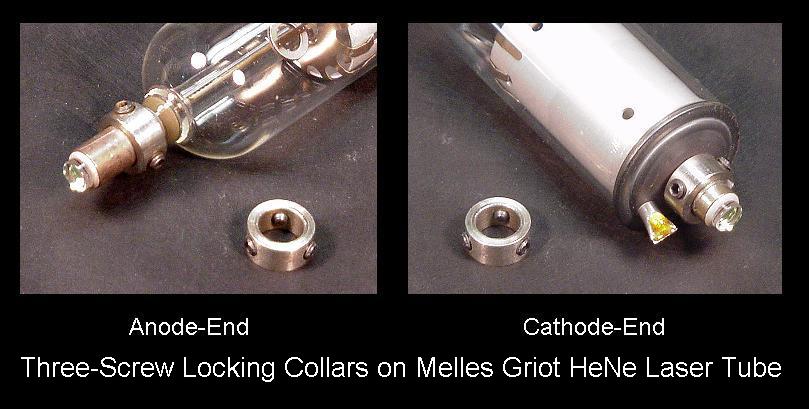
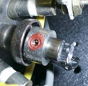
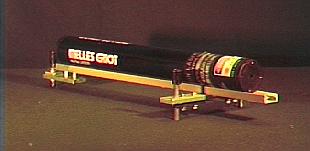
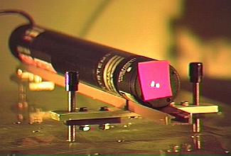
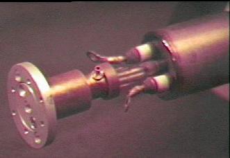
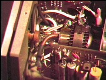
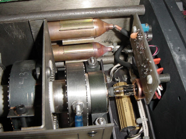
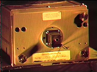
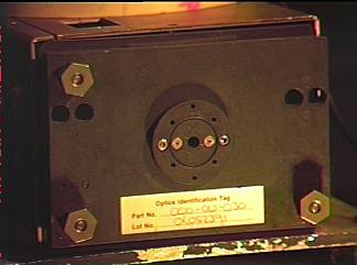
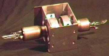